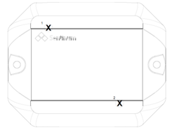
- Help-Desk
- Sensors & Product Lines
- Juno Tracker
Juno Tracker operating instructions
Are you looking for operating constructionsfor Juno Tracker?
General Warnings and Safety Instructions
📢 Please note:
- Follow all safety and installation instructions in the manual and installation list.
- Ensure the installation environment meets all specified temperature and application limits.
- The device may only be used for the purposes and in the areas described in the technical specifications.
- Function and safety are no longer guaranteed if the device is modified or extended.
- Do not mount the sensor on ceilings or floors.
- Operation is allowed only up to 2,000 m above sea level and at a room height ≤ 2 m.
- Maintain a minimum distance of 20 cm between the device and any person.
❗ If the device is installed incorrectly:
- It may fail to operate correctly.
- It may become permanently damaged.
- It may pose a risk of injury.
Please also note:
- Improper mechanical stress (e.g., dropping) can damage the device.
- Using non-approved battery cells can impair performance and product safety.
- Only operate the device if it is undamaged after unpacking; perform a visual inspection immediately after removal.
Intended Use and Product Versions
These operating instructions apply to the entire Juno product series.
There are various product versions within the series, which differ in their localization methods as well as in the equipment and functionality of the sensors. The specific features and functions of the respective versions are explained separately in the rest of this manual.
Item Number | Radio Standard | Functions |
---|---|---|
S-JUNO(-iX)-LOEU | LoRaWAN® | Tilt detection, activity detection, opening & motion detection |
S-JUNO(-iX)-MIOTY | mioty® | Tilt detection, activity detection, opening & motion detection |
S-JUNO(-iX)-LOEU-TH | LoRaWAN® | Temperature, relative humidity, tilt & activity detection, opening & motion detection |
S-JUNO(-iX)-MIOTY-TH | mioty® | Temperature, relative humidity, tilt & activity detection, opening & motion detection |
S-JUNO-NB-TH | NB-IoT | Temperature, relative humidity, tilt & activity detection, opening & motion detection |
S-JUNO(-iX)-LOEU-TRACK | LoRaWAN® | Tilt detection, activity detection, opening & motion detection |
S-JUNO(-iX)-LOEU-TH-TRACK | LoRaWAN® | Temperature, relative humidity, tilt & activity detection, opening & motion detection |
S-JUNO(-iX)-NBM1-TRACK-2 | NB-IoT, CAT-M1 | Tilt detection, activity detection, opening & motion detection |
S-JUNO(-iX)-NBM1-TRACK-3 | NB-IoT, CAT-M1 | Tilt detection, activity detection, opening & motion detection |
S-JUNO(-iX)-NBM1-TH-TRACK-2 | NB-IoT, CAT-M1 | Temperature, relative humidity, tilt & activity detection, opening & motion detection |
S-JUNO(-iX)-NBM1-TH-TRACK-3 | NB-IoT, CAT-M1 | Temperature, relative humidity, tilt & activity detection, opening & motion detection |
S-JUNO(-iX)-MIOTY-TRACK | mioty® | Tilt detection, activity detection, opening & motion detection |
S-JUNO(-iX)-MIOTY-TH-TRACK | mioty® | Temperature, relative humidity, tilt & activity detection, opening & motion detection |
Product Codes and Localization Procedures
Item Number | Radio Standard | WIFI SSID Scan | GNSS Scan | GNSS | Cell Locate | Tracking in the LPWAN |
---|---|---|---|---|---|---|
S-JUNO(-iX)-LOEU | LoRaWAN® | ✖ | ✖ | ✖ | ✖ | ✔ |
S-JUNO(-iX)-MIOTY | mioty® | ✖ | ✖ | ✖ | ✖ | ✔ |
S-JUNO(-iX)-LOEU-TH | LoRaWAN® | ✖ | ✖ | ✖ | ✖ | ✔ |
S-JUNO(-iX)-MIOTY-TH | mioty® | ✖ | ✖ | ✖ | ✖ | ✔ |
S-JUNO-NB-TH | NB-IoT | ✖ | ✖ | ✖ | ✔ | ✖ |
S-JUNO(-iX)-LOEU-TRACK | LoRaWAN® | ✔ | ✔ | ✖ | ✖ | ✔ |
S-JUNO(-iX)-LOEU-TH-TRACK | LoRaWAN® | ✔ | ✔ | ✖ | ✖ | ✔ |
S-JUNO(-iX)-NBM1-TRACK-2 | NB-IoT, CAT-M1 | ✔ | ✖ | ✔ | ✔ | ✖ |
S-JUNO(-iX)-NBM1-TRACK-3 | NB-IoT, CAT-M1 | ✔ | ✖ | ✔ | ✔ | ✖ |
S-JUNO(-iX)-NBM1-TH-TRACK-2 | NB-IoT, CAT-M1 | ✔ | ✖ | ✔ | ✔ | ✖ |
S-JUNO(-iX)-NBM1-TH-TRACK-3 | NB-IoT, CAT-M1 | ✔ | ✖ | ✔ | ✔ | ✖ |
S-JUNO(-iX)-MIOTY-TRACK | mioty® | ✔ | ✖ | ✔ | ✖ | ✔ |
S-JUNO(-iX)-MIOTY-TH-TRACK | mioty® | ✔ | ✖ | ✔ | ✖ | ✔ |
Intended Use
The Juno sensor is a wireless, battery-powered IoT device for recording environmental and motion data. It's designed for industrial and commercial applications—especially condition monitoring and object localization, both indoors and outdoors.
Depending on the variant, the sensor includes different modules (e.g. temperature, movement, inclination) and localization methods (GNSS, Wi-Fi SSID scan, or LoRaWAN-based positioning). It must be used only as described in these instructions and within the stated technical specifications. Any other use is improper, and Sentinum GmbH accepts no liability for resulting damage.
Differences Between the iX Versions
The iX models feature extended industrial certifications, additional accessories, and finer control over measurement and transmission intervals. Standard versions require a minimum 5-minute interval, while iX versions support intervals down to 1 minute. They also differ in housing color.
Version | Housing Color |
---|---|
Standard version | Black |
iX industrial version | Silk grey |
Technical drawing
Juno ( without TH)
Juno TH ( without opening)
Scope of Delivery
Product Version | Scope of Delivery |
---|---|
Standard version |
|
iX industrial versions |
|
Adhesive pad technical drwaing
Approved Batteries and Types
Item Number | Approved Batteries |
---|---|
S-JUNO(-iX)-LOEU/ S-JUNO(-iX)-MIOTY/ S-JUNO(-iX)-LOEU-TH/ S-JUNO(-iX)-MIOTY-TH/ S-JUNO(-iX)-LOEU-TRACK/ S-JUNO(-iX)-MIOTY-TRACK/ S-JUNO(-iX)-LOEU-TH-TRACK/ S-JUNO(-iX)-MIOTY-TH-TRACK |
|
S-JUNO(-iX)-NBM1-TRACK-2/ S-JUNO(-iX)-NBM1-TRACK-3/ S-JUNO(-iX)-NBM1-TH-TRACK-2/ S-JUNO(-iX)-NBM1-TH-TRACK-3/ S-JUNO-NB-TH |
|
Detection and Localization Methods Overview
Item Number | Radio Standard | WIFI SSID Scan | GNSS Scan | GNSS | Cell Locate | Tracking in the LPWAN |
---|---|---|---|---|---|---|
S-JUNO(-iX)-LOEU | LoRaWAN® | ✖ | ✖ | ✖ | ✖ | ✔ |
S-JUNO(-iX)-MIOTY | mioty® | ✖ | ✖ | ✖ | ✖ | ✔ |
S-JUNO(-iX)-LOEU-TH | LoRaWAN® | ✖ | ✖ | ✖ | ✖ | ✔ |
S-JUNO(-iX)-MIOTY-TH | mioty® | ✖ | ✖ | ✖ | ✖ | ✔ |
S-JUNO-NB-TH | NB-IoT | ✖ | ✖ | ✖ | ✔ | ✖ |
S-JUNO(-iX)-LOEU-TRACK | LoRaWAN® | ✔ | ✔ | ✖ | ✖ | ✔ |
S-JUNO(-iX)-LOEU-TH-TRACK | LoRaWAN® | ✔ | ✔ | ✖ | ✖ | ✔ |
S-JUNO(-iX)-NBM1-TRACK-2 | NB-IoT, CAT-M1 | ✔ | ✖ | ✔ | ✔ | ✖ |
S-JUNO(-iX)-NBM1-TRACK-3 | NB-IoT, CAT-M1 | ✔ | ✖ | ✔ | ✔ | ✖ |
S-JUNO(-iX)-NBM1-TH-TRACK-2 | NB-IoT, CAT-M1 | ✔ | ✖ | ✔ | ✔ | ✖ |
S-JUNO(-iX)-NBM1-TH-TRACK-3 | NB-IoT, CAT-M1 | ✔ | ✖ | ✔ | ✔ | ✖ |
S-JUNO(-iX)-MIOTY-TRACK | mioty® | ✔ | ✖ | ✔ | ✖ | ✔ |
S-JUNO(-iX)-MIOTY-TH-TRACK | mioty® | ✔ | ✖ | ✔ | ✖ | ✔ |
How Wi-Fi SSID Scanning Works
- Passive scan: Listens for beacon frames carrying SSID, BSSID and RSSI.
- RSSI measurement: Evaluates signal strength to estimate proximity to each access point.
- Trilateration: Uses RSSIs plus known AP locations to compute device position.
- Refinement & display: Applies environmental and motion adjustments; updates map in real time.
Advantages & Applications
- Indoor accuracy where GPS is weak or unavailable
- Low cost by leveraging existing Wi-Fi infrastructure
- Energy-efficient: no continuous satellite lock needed
Key use cases:
- Indoor navigation (malls, airports)
- Asset & fleet tracking (warehouses, campuses)
- Battery-sensitive IoT positioning
Factors Affecting Accuracy
- Signal variability: RSSI–distance is non-linear and distorted by walls, furniture, interference.
- AP density & placement: ≥3 well-spaced APs needed for reliable trilateration.
- Algorithm quality: Calibrated or ML-based methods can smooth noise.
- Open areas: ~1–5 m accuracy
- Complex interiors: ~5–20 m accuracy
Why Juno Benefits
- Hybrid positioning: Combines Wi-Fi SSID, GNSS & cellular data
- Dual-band scan: Active/passive on 2.4 GHz & 5 GHz; up to 20 APs
- Battery-friendly: Optimized for low power, extends device life
- Secure: WPA3 support
- Realistic accuracy: 3–20 m depending on environment
How GNSS Scanning Works
- Satellite lock: Receives signals from ≥4 satellites (GPS, Galileo, GLONASS, BeiDou)
- Time-of-flight: Distance = speed of light × signal transit time
- Trilateration: Intersects spheres around satellites to derive position & time
- Correction systems: DGPS/SBAS reduce atmospheric, orbital & clock errors
Typical accuracy: Single GNSS: 2.5–10 m; Multi-GNSS: 1–3 m (urban canyons up to 10–50 m)
GNSS & Wi-Fi Data in LoRa® Cloud
- Data ports: Wi-Fi SSID scan (194), GNSS scan (197)
- Workflow: Device → LoRa® Cloud → Geolocation → Network server
- Integrations: Semtech LoRa Cloud, The Things Stack (TTI), ChirpStack
📋 Prerequisites
- An active account at The Things Stack (TTI).
- A registered LoRaWAN device (e.g. a tracker with GNSS).
- API access to Semtech LoRa Cloud Services (via Dev Portal: https://lora-developers.semtech.com).
- LoRa Cloud Token (API key) from the LoRa Cloud Portal.
Activate Semtech LoRa Cloud
- Go to https://lora-developers.semtech.com.
- Create an account or log in.
- Under LoRa Cloud → Modem Services, copy your token (API key) for later use.
Set Up Integration in The Things Stack
- Log in to The Things Stack Console (e.g. https://eu1.cloud.thethings.industries/).
- Open the device you want to connect.
- Go to Integrations → Webhooks.
- Click Add Webhook and select Semtech LoRa Cloud as the template.
Configure Webhook
- Fill out the form:
- Base URL: Automatically suggested by TTI.
- Token: Your API key from LoRa Cloud.
- Activate desired services, e.g.:
- Modem Services (GNSS & Wi-Fi scans)
- Geolocation (TDOA/RSSI)
- You can also send GNSS or Wi-Fi data, depending on the device.
Adapt Payload Formats (if necessary)
- Ensure your end device uses Semtech's expected payload structure (e.g. LoRa Basics Modem format).
Check Data
- Once your device sends position data, it's forwarded from TTI to LoRa Cloud.
- The Cloud's response is then returned via TTI to your device or application.
Test & Monitoring
- Use TTI's Live Data view to verify transmissions.
- In Semtech Cloud, check incoming and processed requests.
- Inspect response packets for geodata (latitude, longitude) and accuracy.
❗ Note: This integration works best with devices based on Semtech's LoRa Basics Modem-E architecture (e.g. LoRa Edge™ LR1110), but custom formats are also possible if API requests are compatible.
Port Assignment for Wi-Fi SSID Scan, GNSS Scan & Regular Payload
Feature | LoRaWAN Port | Description |
---|---|---|
GNSS Scan Payload | 197 | Raw data (satellite ID, time, etc.) to geolocation backend. |
Wi-Fi SSID Scan Payload | 194 | Scanned MAC addresses + RSSI for localization. |
Regular Payload | 1 | Standard sensor data: temperature, humidity, angle, battery voltage, etc. |
The following providers can be recommended for decoding the WIFI SSID SCAN and GNSS SCAN data:
- Semtech LoRa Cloud (discontinued at the end of July 2025)
- AWS
- Tencent
- Traxmate
- Sentinel
Local databases can be used for on-prem applications
Tracking in the LoRaWAN®
Tracking in LoRaWAN® relies on "nodes" broadcasting radio signals to multiple gateways. The network (or a positioning cloud like Semtech LoRa® Cloud) computes position by evaluating these signals—rather than the device locating itself. Different methods (or combinations) are chosen per use-case and infrastructure.
TDOA (Time Difference of Arrival)- How it works: Each gateway stamps a node's transmission time with nanosecond precision.
- Multilateration: Pairwise time differences define hyperbolas; ≥ 3 gateways yield an intersection (latitude/longitude).
- Processing: Calculation happens centrally (network server or cloud).
- Typical accuracy: ~200–1 000 m, improving with gateway density, sync quality, and favorable environment.
Gateways must use GPS or PTP (Precision Time Protocol) to maintain precise time sync— even microsecond drift leads to large distance errors.
Key Accuracy Factors:
- Gateway density & geometry
- Time‐synchronization precision
- Environmental conditions (e.g. multipath from buildings)
- Signal distortion by walls, furniture → timing errors
- Multipath echoes alter arrival times
- Line-of-sight: Hard to place ≥ 3 clear gateways indoors
- GPS sync: Often unreliable inside buildings
- Very large indoor spaces (warehouses, terminals) with dense gateway coverage
- Using multipath-aware error-correction algorithms
- In hybrid setups—combining LoRaWAN® TDOA with Bluetooth, UWB, or Wi-Fi—to boost precision
Tracking via the "Cell Locate" Mobile Network
Mobile phone positioning works by a device communicating with the cellular network via its radio signal. The network then estimates location based on various parameters. Below is an overview of the key methods:
Method | Typical Accuracy | Remark |
---|---|---|
Cell ID | 100 m – several km | Very rough; depends on cell size (city vs. country) |
Enhanced Cell-ID | 50 – 500 m | Better through timing info, but network-dependent |
TDOA (Time Difference of Arrival) | 50 – 150 m | Requires several synchronized stations |
AOA (Angle of Arrival) | 100 – 200 m | Less common; requires special antennas |
The accuracy of mobile-network positioning depends heavily on the chosen method, network coverage, and environmental factors. Power consumption is very low compared to other positioning technologies.
eDRX: On the Way to the Interrogable Tracker
eDRX (Extended Discontinuous Reception) is available only on mobile devices.
The goal of an always-listening, remotely interrogable tracker is now within reach thanks to eDRX.
How eDRX Works- Sleep mode: After transmitting, the device pauses its regular network checks.
- Extended intervals: Instead of polling every few seconds, it can listen only once per minute—or even per hour—for incoming messages (e.g., location queries).
- Wake-up cycle: At each eDRX epoch, it briefly reactivates its receiver, processes any commands, then returns to sleep.
- Drastically lower energy use during idle periods
- Maintains network registration (not fully offline)
- Enables on-demand querying of device location or status
- Cycle length: Ranges from seconds to hours (operator-dependent).
- Trade-off: More frequent wake-ups raise the device's quiescent current.
- Optimization: Balance polling interval against battery life to meet the intended service duration.
🛠️ General Handling Instructions
- 📦 Transportation & Storage
- Transport and store the sensor in its original packaging to avoid mechanical damage and static discharge.
- Store the device according to the parameters specified in the technical data sheet.
- 🔧 Assembly
- Only use the mounting points provided on the housing for fastening.
- Ensure a stable, vibration-free mount to maintain measurement accuracy.
- 🚀 Commissioning
- Insert battery correctly and ensure it has sufficient charge.
- Activate the sensor using the integrated magnetic switch or the smartphone app (model-dependent).
- Use Sentinum's software/app for initial configuration.
- ⚙️ Operation
- Operate only within specified ambient conditions (temperature, humidity, protection class).
- Avoid strong magnetic fields or metallic shielding that could impair radio communication or sensor functions.
- 🧼 Cleaning
- Clean housing with a slightly damp, lint-free cloth if necessary.
- Do not use aggressive cleaners or solvents.
- Tracker versions (non-TH, without opening) are IP69k approved and can be cleaned accordingly.
- 🔋 Maintenance
- Juno sensors are low-maintenance; battery replacement is required after several years, depending on use.
- Regularly check functionality and backend connection.
- ♻️ Waste Disposal
- At end of service life, dispose of the device per local electronics and battery recycling regulations.
⚠️ Special Handling Instructions for -TH Versions
The Juno TH versions feature a delicate membrane that allows air exchange for precise temperature and humidity measurements. Follow these guidelines to protect its integrity:
- The membrane is sensitive to mechanical stress—never insert pointed or sharp objects into the opening.
- Avoid contamination from chips, dust, or particles—clogs impair measurement accuracy.
- Do not attempt to clean or replace the membrane yourself. Contact the manufacturer or authorized specialist.
- Keep cleaning agents away—aggressive chemicals can permanently damage or alter membrane permeability.
- Even with IP67 protection, ensure no water accumulates at the membrane opening—standing water skews readings.
- For outdoor use, mount at a ≥45° angle so the membrane faces downward.
- Keep the sensor away from ground level and splash zones to prevent dirt, mud, or water ingress.
- Ensure air circulation: Avoid fully enclosed housings or heavy shielding; free airflow is essential.
- Avoid UV exposure: Prolonged sunlight can degrade the housing and membrane—install in partial shade or under a small cover.
- Avoid condensation: Large temperature swings can cause moisture build-up at the opening—maintain downward-facing installation.
- Do not paint or coat: Even thin layers can seal the membrane and lead to significant errors.
- Avoid aggressive atmospheres: High concentrations of solvent vapors, sulfur compounds, etc., can damage the membrane and electronics unless explicitly approved.
🛠️ Assembly and Installation
🚨 Warning and Safety Instructions for InstallationIf the sensor is still easily accessible after installation, install the sensor first and activate it after installation!
If the sensor is no longer accessible after installation, first activate the sensor and then install it after activation!
Before mounting the sensor in this way, make sure that the surface on which it is to be screwed is flat, otherwise the housing may be damaged.
Please note:
- Do not insert any objects or body parts into the openings of the sensor.
- Do not mount the sensor on the ceiling or floor.
- Do not install the sensor at heights above two meters.
- Only install the sensor indoors on a wall in a standard room at a height of 1.50 m to 1.80 m.
- Protect hands and fingers: Strong magnets can suddenly attract and pinch skin—keep sufficient distance and wear protective gloves if necessary.
- Keep electronic devices away: Magnetic fields can damage smartphones, credit cards, pacemakers, etc.
- Be aware of breakage: Many magnets are brittle—avoid impacts to prevent sharp splinters.
- Health risks: Those with implanted medical devices should avoid strong magnets or consult a doctor.
- Store safely: Keep magnets separated from each other and metal objects to prevent uncontrolled attraction.
- Danger for children: Small magnets are not toys—keep out of reach to avoid ingestion hazards.
- Avoid heating: Do not expose magnets above their max operating temperature (80–200 °C).
Mounting Type | Description | Recommended Accessories |
---|---|---|
Screw connection | 2 × M4 or M5 screws | 2 × suitable countersunk-head screws (wood screw 4–5 mm if necessary) |
Magnets | 2 × neodymium pot magnets M4, internal thread | 2 × neodymium magnets (indoor) – total 16–32 kg load capacity |
Gluing | Double-sided adhesive tape or mounting adhesive | High-strength double-sided tape or approved mounting adhesive |
🛠️ General Installation Instructions
🧩 Installation of the Juno Tracker Versions (without opening)- Select an installation location that is within the specified ambient temperatures and conditions (see technical data).
- Do not cover the housing: Radio communication (e.g. LoRaWAN®, BLE) must not be obstructed by metallic objects, sealed housings or structure-shielding materials.
- Ideally, mount the sensor with a clear line of sight to the sky to ensure smooth operation of the radio interfaces.
- Mount the sensor securely, ideally using the mounting holes provided; choose low-vibration or solid surfaces.
- Alignment: The standard version does not require special alignment and can be mounted flat, vertically, or horizontally, depending on the application.
- Do not install near strong electromagnetic sources to avoid signal interference.
- Always mount the sensor at an angle of ≥45° so the membrane points downward—prevents water or dirt from collecting in the opening.
- Do not install close to the ground or in splash-water areas; mount elevated and protected from direct dirt entry.
- Select a location with free air circulation; avoid enclosed housings without ventilation.
- Avoid direct sunlight to prevent overheating and measurement distortion; use partial shading or a small weather cover.
- Avoid dusty or chip-filled environments (e.g. workshops, grinding stations) to protect the membrane.
- Never seal, glue, or paint over the membrane opening.
- Allow only authorized specialists to clean or replace the membrane in consultation with the manufacturer.
- Mount the GNSS sensor outside of metal housings for optimal satellite reception.
- Avoid installing near metal surfaces or large metallic structures.
- Ensure a clear line of sight to the sky for best GNSS performance.
- Keep at least 30 cm clearance from metallic materials in front and to the sides.
- Place the sensor away from high-voltage power lines and strong electromagnetic fields.
- Avoid closed rooms or covers that could block GNSS signals.
- If used as a mobile device, ensure the sensor is firmly secured during operation.
📡 Important Note for Devices with External Antenna
If you have ordered a device with an external antenna, which can be recognized by the gold RP-SMA connector, first install the antenna included in the scope of delivery.
- 📡 External antenna: Please note that the antenna should always be mounted vertically and that the tip should point to the sky if the application permits. The antenna should be at least 2 cm away from metal surfaces. Make sure that the antenna is not shielded by surrounding metal parts, if the application allows this.
- 📶 Internal antenna: If your device has an internal antenna (no external antenna visible), the sensor should always be mounted with the long side vertical, as this allows the maximum signal strength of the device to be achieved. The antenna is located on the top (logo side) of the housing and should be at least 2 cm away from metal surfaces. Ensure that the antenna is not shielded by surrounding metal parts, as far as the application allows.
- ⚠️ Please note: If you receive a device with an external antenna, never operate the device without an external antenna! This can lead to irreparable damage to the sensor.
🪛 Wall Mounting with Screws
The Juno sensor can be securely and permanently mounted on a wall or other solid surface. It is mounted using the screw holes provided in the housing flange.
Preparation for assembly:
- Determine the mounting position: Select a mounting location that is low-vibration, dry and suitable for the sensor function (e.g. free air circulation for TH versions).
- Check the mounting surface: Solid substrates such as concrete, masonry, wood or technical plastic panels are suitable. Use suitable dowels for porous substrates.
- Provide tools:
- 🔧 Cordless screwdriver or screwdriver with torque control
- 🔧 Drill bit (suitable for the wall texture)
- 🔧 Dowels (if required)
- 🔧 Screws (see below)
🪛 Screw Selection
- The mounting holes in the sensor housing are designed for M4 screws.
- Depending on the mounting surface, we recommend
- M4 cylinder head screws (e.g. DIN 912, stainless steel) for plastic housings or metal frames
- Spax screws43 mm with suitable plugs for concrete, brick or timber walls
- The screw must be able to pass freely through the housing without distorting or damaging the housing.
- Maximum tightening torque: 3 Nm. A higher torque can lead to housing deformation or breakage.
- Tighten the screws evenly and without tension.
- Ensure that the housing lies flat without mechanical stresses building up.
- Do not drill any additional holes or modify the housing.
- Do not mount upside down if condensation or dirt could collect in the sensor area.
- Wear suitable protective equipment during installation (e.g. safety goggles for drilling work).
- Check that it is correctly attached by gently pulling and pushing on the housing.
- Make sure that no cables or electrical lines behind the wall are damaged.
- For TH versions: Observe the recommended tilt angle (min. 45°) and the downward orientation of the membrane.
📋 Prerequisites and Preparation
- The mounting surface must be even, stable, clean, dry and grease-free.
- Before application, clean the surface with isopropanol or a suitable plastic cleaner.
- The adhesive strip should not be used on porous, textured or very uneven surfaces, as adhesion will be impaired.
🛠️ Assembly Instructions
- Remove the protective film from one side of the adhesive strip and apply the strip flat to the back of the sensor. Placement can be based on the markings provided. Make sure that the strip is positioned exactly and that there are no air pockets.
- Then remove the second protective film and apply the sensor to the prepared surface with even pressure (approx. 10–15 seconds).
- The sensor should adhere undisturbed for at least 24 hours to achieve full adhesive strength.
⚠️ Important Notes
- The adhesive connection is designed for long-term use indoors or in protected outdoor areas.
- Adhesive performance may be impaired in environments with high UV exposure, moisture, high heat (> 80 °C) or constant vibration.
- Subsequent correction of the position after application is only possible to a very limited extent.
- For TH versions, the recommended mounting position (at least 45° inclined, membrane facing downwards) must also be observed for adhesive mounting in order not to jeopardize the functionality of the sensor membrane.
- The adhesive strips are not reusable. A new adhesive strip must be used when moving the sensor.
🔌 Commissioning and Use
Please note that the housing or electronics may be damaged if knives or other sharp objects are used.
🧲 Commissioning the Sensor with MagnetThere is a magnetic field switch on the sensor for easy activation of the sensor. The following graphic shows the position of the magnetic field switch.
Item number |
Approved batteries |
S-JUNO(-iX)-LOEU/MIOTY S-JUNO(-iX)-LOEU/MIOTY-TH S-JUNO(-iX)-LOEU/MIOTY-TRACK S-JUNO(-iX)-LOEU/MIOTY-TH-TRACK S-JUNO(-iX)-NBM1-TRACK-2 S-JUNO(-iX)-NBM1-TRACK-3 S-JUNO(-iX)-NBM1-TH-TRACK-2 S-JUNO(-iX)-NBM1-TH-TRACK-3 S-JUNO-NB-TH
|
![]() |
To activate the sensor, hold a commercially available magnet to the point marked X. A neodymium magnet with a minimum surface area of 1 cm² is recommended. The magnet must remain in place for at least 2 seconds until the device is activated. This is acknowledged with a beep.
💡 Note: For operation, please note that Hall switch 1 can always be used to detect a damper opening and magnetic switch 2 is always triggered to activate or advertise the BLE.
📶 Commissioning the Sensor via BLE (Quick Guide)
This activation via BLE only applies to the article numbers:
- S-JUNO(-iX)-LOEU/MIOTY-TRACK
- S-JUNO(-iX)-LOEU/MIOTY-TH-TRACK
- S-JUNO(-iX)-NBM1-TRACK-2
- S-JUNO(-iX)-NBM1-TRACK-3
- S-JUNO(-iX)-NBM1-TH-TRACK-2
- S-JUNO(-iX)-NBM1-TH-TRACK-3
- Set the sensor to BLE advertising mode so that the Juno can be recognized and found by BLE-enabled end devices.
To activate advertising mode, hold a standard magnet to the point on the housing marked with an X in the image on the right:
- Hold the magnet close to the housing for at least 2 seconds,
- or briefly place it directly on the marked position.
Advertising mode is then started automatically.
📲 Commissioning the Sensor via NFC
This activation only applies to article numbers:
- S-JUNO(-iX)-LOEU/MIOTY
- S-JUNO(-iX)-LOEU/MIOTY-TH
- S-JUNO-NB-TH
Activation takes place via an NFC app. A smartphone is required for this. The app can be downloaded from the respective app stores. Simply search for "Sentinum LinQs" and download the LinQs app.
First locate the tag on the sensor and then the reader on your end device. The position of the NFC tag can be found at the position of the orange arrow.
The location of the tag is also marked on the top and labeled "Tap here". You can also see the position of the NFC tag in the technical drawing.
Open the app and activate the sensor. To start the sensor in the basic settings, click on the "Activate sensor" button in the app's start menu. Now place your device on the NFC mark on the sensor.
When the sensor is activated, "Sensor updated!" is displayed. You can then continue with the activation of the other sensors.
Step | Description |
![]() |
Activate the sensor : Use the "Activate Sensor" button to activate the sensor and enable BLE advertising mode for the sensor |
![]() |
Read and set parameters via NFC: Use the "Read" button to read out the parameters |
![]() |
Set the value via NFC : Tap the desired table entry and change the values. Confirm with the button below "Update & Reboot" or "Update". Update and reboot forces a reboot in addition to the change, update is used for the next measurement or transmission |
Commissionning the sensor via BLE
Step | Description |
![]() |
Activate BLE Advertising: The BLE advertising mode can be activated with the magnet or after activating the sensor. |
![]() |
Search for BLE device: Use the "Search" button to search for the sensor via BLE . |
![]() |
Connect to the sensor via BLE: Select the correct sensor and confirm by clicking on "juno". |
![]() |
Connect to the sensor via BLE: Click on the "Connect" button. |
![]() |
Configure with the sensor via BLE: Now use the "Configure" button to set parameters. |
![]() |
Configure with the sensor via BLE: A transmission can be triggered using the "Trigger Send" button. Tap the desired table entry and change the values. Confirm with the button below "Update & Reboot" or "Update". Update and Reboot forces a reboot in addition to the change, Update is used for the next measurement or transmission. |
🔊 Audible Signal and Feedback
- When the device is switched on, an acoustic signal consisting of several ascending tones sounds. This sequence of tones signals that the sensor has been successfully activated.
- When the device is switched off, several descending tones are played to acoustically confirm that the device has shut down.
- When establishing or disconnecting a Bluetooth connection (BLE), the sensor also emits an acoustic signal to confirm the connection status.
⚙️ Sensor Functions
Specific sensor functions for the Juno are explained below.
🔄 HysteresisHysteresis describes a behavior in which the reaction of a system depends not only on its current state, but also on its previous history. This means that the system "remembers" where it came from - and therefore reacts differently to the same stimulus, depending on whether the stimulus is currently increasing or decreasing.
Hysteresis = delay or difference in behavior when a signal or stimulus is increased or decreased.
Two hysteresis limit values are specified for the Juno, one for the temperature and one for the relative humidity. The values are applied to both the delta and the absolute limit values.
Description:
- Orange line: Sensor values over time.
- Red lines:
- Dashed (--): Maximum alarm threshold value (e.g. 30° C).
- Dotted (---): Reset point with falling temperature (e.g. 28° C).
- Blue lines:
- Dashed (--): Minimum alarm threshold value (e.g. 10° C).
- Dotted (---): Reset point when the temperature rises (e.g. 12° C).
Example procedure:
- The sensor triggers a "MAX alarm" as soon as the value is ≥ 30 °C.
- The alarm remains active until the value falls below 28 °C→ only then is it reset.
- Conversely, the same applies to the lower range with the "MIN alarm" at ≤ 10 °C.
The behavior prevents alarms from being constantly triggered or deactivated in the event of minimal fluctuations - typical for hysteresis.
Tracking and Tracking in Motion
The localization of the device is independent of the transmission of the sensor data (e.g. temperature, tilt angle or relative humidity).
This means that
The interval for determining the location can be freely configured without changing the transmission intervals of the sensor data.
The measured values from the sensors are recorded and transmitted regardless of the tracker's movement status - whether the device is in motion or stationary.
The device is located either at fixed intervals or event-controlled, e.g. by detected movement or other activity parameters.
Tilt and Tilt Detection
Two operating modes are available for the Juno sensors with integrated tilt detection:
- Ultra-low power tilt detection
This mode is characterized by a particularly low power consumption of only 1 µA. It reliably detects a tilt or damper opening from approx. 50 degrees. Ideal for applications where coarse tilt detection is sufficient and energy efficiency is paramount. - Advanced tilt detection
In addition, an advanced mode is available that enables the precise detection of inclinations or flap openings. The power consumption here depends on the selected scanning frequency, but is higher than that of the ultra-low power variant. This mode is suitable for applications with higher accuracy requirements.
The tilt and opening detection and tracking in motion functions are mutually exclusive.
This means that a sensor with tracking in motion activated cannot perform real-time tilt or flap opening detection.
However, the current tilt angle is still transmitted regularly so that the position can be evaluated retrospectively.
Communication with the interface
The option to configure the sensor communication and the join behavior can be found in the respective generic LoRaWAN® , Mioty® or Cellular (NB-IoT and LTE-M1) documentation, depending on the version.
You can also find all documents relating to generic documentation at https://docs.sentinum.de/wichtig-produktübergreifende-dokumentation-für-sensoren.
Care and Cleaning
To ensure that the sensor functions reliably and has a long service life, it should be maintained regularly. Please observe the following instructions:
- Clean the housing, especially the ventilation slots of the sensor, with a dry or slightly damp microfiber cloth. Make sure that no moisture penetrates the device.
- Carry out cleaning regularly, especially in dusty or pollen-rich environments, to ensure the long-term functionality of the sensor.
- Do not use cleaning agents containing alcohol or solvents, as these can damage the surface of the sensor.
- Do not use compressed air or other intensive cleaning methods, as these can damage sensitive sensor components.
- Hard deposits (e.g. limescale, oil or grease) can impair the measuring accuracy. If necessary, clean early with a soft, damp cloth and mild detergent.
- Make sure that there are no leaves, water or snow on the sensor. This can negatively affect the performance of the sensor.
Battery change
- Open the 4 screws on the back of the sensor marked with the orange arrows. You will need a Torx T10 screwdriver for this and make sure that the seal is not damaged.
-
Remove the back of the sensor housing. Check that the seal is in place and take care not to damage it when opening it
-
Remove the old batteries from the battery holder.
-
Insert 2 new battery cells. If cells other than those recommended are used, performance and product safety may be impaired and the running times and performance specified in the data sheets may not be achieved. After insertion, the sensor should start with a short beep. As soon as you hear this signal, replace the back of the housing.
-
Place the rear panel back on the top of the housing. Make sure that the seal is properly seated and that the housing can be closed properly.
- Screw the housing together. Tighten the screws crosswise to ensure even and tension-free fastening. Make sure that the original position of the seal has not been changed. Then reinstall the sensor at its place of use. Dispose of the old batteries in an environmentally friendly manner.
Flap openning detection and TILT detection
The flap opening detection can be carried out either via the magnetic switch or the acceleration sensor. Tilt detection (tilt feature) is carried out via the acceleration sensor.
Flap detection VIA the magnetic switch
For Operation
For operation, please note that Hall switch 1 can always be used to detect a damper opening and magnetic switch 2 is always triggered to activate or advertise the BLE.
- The magnetic field switch is active. Either one or both sensors can be used.
- Large neodymium magnets are recommended. These should be attached as close as possible to the sensor. A recommended distance between the magnet and the sensor cannot be specified universally due to the variable size of the magnet. A maximum distance of 1 cm between the magnet and the housing is recommended.
- For comparison: With a neodymium disk magnet with d = 20mm and h = 5mm, reliable values are achieved at distances of less than 1 cm.
- The magnetic field switches can be operated in three different modes:
- Container is closed when the solenoid is applied.
- The container is open when the magnet is applied.
- The sensor counts an opening when the magnet passes through twice.
Flap Opening Detection with Acceleration Sensor and Tilt Detection
The Juno sensor is equipped with an integrated 3-axis acceleration sensor of the type used for the reliable detection of changes in movement and position. One of the key functions of this sensor is to detect the opening of flaps, lids or housings, as typically found in industrial applications.
- Position detection in idle state:
- When the flap is closed, the sensor is in a defined, stable position.
- The LIS2DTW12 continuously measures acceleration along the X, Y and Z axes.
- The absolute position of the flap can be clearly identified via the so-called static acceleration (mainly caused by the earth's gravity).
- Change of inclination or movement:
- If the flap is opened or moved, the orientation of the sensor in the room changes.
- The sensor recognizes this change by a clear deviation of the measured acceleration values on at least one axis.
- This change is interpreted as a trigger event.
- Threshold-based detection:
- A tilt angle or a movement threshold can be defined in the Juno firmware setup (e.g. change by 15, not ultra-low power operation The sensor can of course be operated in a very energy-saving manner by setting the measurement frequency of the angle to a correspondingly high value, e.g. 5 minutes. The measurement is then insignificant in relation to the remaining power consumption.
- As soon as the measured values exceed this threshold value, a damper opening event is registered.
- Optional: Interrupt-controlled operation:
- The sensor supports low-power modes with interrupt triggering.
- This means that the sensor remains in a low-power state and only triggers an interrupt to the microcontroller when movement is detected - ideal for extending battery life.
- Disadvantage: The angle cannot be adjusted and is fixed at 65°
- Event processing and data transmission:
- After a detected opening, the event is logged in the internal memory.
- Depending on the configuration, a data packet can be sent immediately via LoRaWAN, BLE or another network protocol to report the event.
Advantage of this method
- No mechanical components required (compared to reed or magnetic switches)
- Insensitive to magnetic field interference
- Simple retrofitting or adaptation via software
Orientations
LoRaWAN specific features
LoRaWAN Join behavior
Before telemetry data can be sent via LoRaWAN, the device must establish a connection with the network. To do this, the device sends join requests until a join accept has been successfully received. As a compromise between energy consumption and a fast join, the transmission intervals of the join requests become longer and longer. In addition, the data rate is also varied (initially large data rate or small spreading factor, then smaller data rate or larger spreading factor). The join behavior strictly adheres to the specifications and recommendations of the LoRa Alliance specification. Sentinum sensors implement the specifications by means of so-called join bursts, the distance between which increases.
A join burst consists of a maximum of 6 join requests with decreasing data rate (DR5-DR0) or increasing spreading factor (SF7-SF12). The intervals between the requests increase quadratically in order not to violate the Lora-Alliance specific duty cycle guidelines. The LoRa Alliance prescribes a decreasing duty cycle for join requests according to the following table Time duty cycle <1h 1% <11h 0.1%
This means that in the first phase (<1h) the same amount of transmission budget is available as in the second (<11h), although only a tenth of the time is available. In order to make maximum use of the budget, the intervals between join bursts (consisting of max. 6 join requests) are initially small and then become larger. Specifically, 2 bursts are carried out in phase 1. In phase 2, 2 further bursts are carried out, and from phase 3 onwards, 1 burst is carried out per day. The length of the bursts increases from approx. 10 minutes in phase 1, to approx. 100 in phase 2, to up to 16 hours in phase 3.
Specifications subject to change without notice. All information provided without guarantee.