![Logo_quer_farbig.png]](https://docs.sentinum.de/hs-fs/hubfs/Logo_quer_farbig.png?height=40&name=Logo_quer_farbig.png)
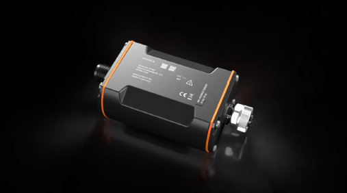
Thank you for choosing the AION420 sensor from Sentinum. Please read the following operating instructions carefully to prevent damage to the sensor, yourself, and the environment.
- General Warnings and Safety Instructions
- Additional Documentation
- Intended Use
- Product Versions
- Scope of Delivery and Mounting Accessories
-
Installation, Assembly, and Wiring
- 6.1 Important Components
- 6.2 Connection Diagram and Pin Assignment (Sensor Side)
- 6.3 Connection Diagram and Pin Assignment (Supply Side)
- 6.4 Warning and Safety Instructions for Mounting
- 6.5 Recommended Mounting Methods
- 6.6 Mounting Accessories
- 6.7 General Installation Instructions
- 6.8 Wiring and Assembly
- 6.9 Suspended Mounting
- 6.10 Installation with a Mounting Clip
-
Commissioning and Configuration
- 7.1 Commissioning and Configuration of the Sensor via BLE
- 7.2 Audible Signal and Flashing Pattern
-
Communication with the Interface
- 8.1 LoRaWAN Join Behavior
- 8.2 mioty Join Behavior
- Maintenance and Cleaning
- Labeling and Certification
Immediate danger. Highly likely to result in death or serious injury.
Dangerous situation. May cause serious injury.
Risk. May result in minor injuries or property damage.
Tips and additional information.
- Follow the safety instructions and installation instructions in the manual and the installation checklist.
- Ensure that the installation environment complies with the specified operating range guidelines. Adhere to the temperature and other limit values at all times.
- The device may only be used within the ranges specified in the technical specifications.
- The device may only be used for the intended purpose and within the specified operating ranges.
- Safety and functionality can no longer be guaranteed if the device is modified or upgraded.
- The sensor must not be mounted on ceilings or floors.
- Operation of the sensor is permitted only up to a maximum altitude of 2,000 meters above sea level.
- Due to human exposure regulations, a minimum distance of 20 cm must be maintained between the device and people.
- Ensure that the installation environment complies with the prescribed guidelines for the intended application. Observe the temperature and other limit values at all times.
- Ensure that the installation environment complies with the prescribed guidelines for the intended application. Adhere to the temperature and other limit values at all times.
- Dispose of the device in accordance with national environmental regulations.
- Repairs to the device may only be performed by the manufacturer.
- Observe the specific safety instructions for batteries and lithium primary cells.
If the device is installed incorrectly:
- It may not function properly.
- It could be permanently damaged.
Please note:
- Improper handling, such as excessive mechanical stress—for example, dropping the device—can result in damage.
- If battery cells other than those recommended are used, this may negatively affect performance and product safety.
If the device is installed incorrectly, it could pose a risk of injury.
Improper handling of lithium batteries (e.g., damage, incorrect charging, short circuits, or high temperatures) can lead to fire, explosion, or injury . Improper handling includes, in particular, mechanical damage, overcharging, deep discharge, short-circuiting, operation outside the specified temperature ranges, and use or disposal not in accordance with the intended purpose.
2. Additional Documentation
Please refer to the information and limit values in the technical data sheet.
The sensor-specific factory settings (Sentiface) as well as the keys and permissible values for the sensor can be found in the NFC and Downlink Description .
The Senticom and Sentivisor tables can be found in the Generic NFC and Downlink Documentation .
The special functions for vandalism detection and opening detection are also generic.
Depending on the version, you can find instructions for configuring sensor communication in the respective generic LoRaWAN® , Mioty® or Cellular (NB-IoT and LTE-M1) documentation.
All documents related to the generic documentation can be found at https://docs.sentinum.de/wichtige-produktuebergreifende-dokumentation-fuer-sensoren .
3. Intended Use
The AION420 is an industrial 4–20 mA bridge for acquiring, digitizing, and wirelessly transmitting measurement values from existing analog 4–20 mA sensors. The device enables the connection of industrial, building automation, energy, and water management sensors to LPWAN wireless networks such as LoRaWAN® or mioty®, without requiring the replacement of existing sensors or controllers.
The AION420 is designed for use with passive 2-wire and active 3-wire sensors and can measure parameters such as level, pressure, flow, temperature, humidity, pH, conductivity, and other process values provided via a 4–20 mA signal.
The device is intended exclusively for the acquisition and transmission of sensor signals within industrial and commercial applications. The analog 4–20 mA signal can continue to be used in parallel by PLCs, SCADA, or process control systems.
The AION420 is intended exclusively for installation in protected indoor areas. Installation typically takes place in control cabinets, distribution cabinets, or comparable protected electrical equipment. The device is not intended for direct, permanent installation in unprotected outdoor areas.
Use is permitted only within the electrical, mechanical, and environmental limits specified in the technical data. Any use beyond these limits is considered improper. In particular, the device must not be used in safety-critical applications where a malfunction could result in personal injury, environmental damage, or property damage.
4. Product Versions
| Item Code | Class | Model | Configuration | Interface |
|---|---|---|---|---|
| S-AION-LOEU-420 | LoRaWAN Class A | Terminated | BLE | 4–20 mA (2 channels) |
| S-AION-MIOTY-420 | mioty Class A | Terminated | BLE | 4–20 mA (2 channels) |
| S-AION-LOEU-420-3L | LoRaWAN Class A | Loop | BLE | 4–20 mA (2 channels) |
| S-AION-MIOTY-420-3L | mioty Class A | Loop | BLE | 4–20 mA (2 channels) |
5. Scope of Delivery and Mounting Accessories
| Part Number | Recommended Accessories |
|---|---|
| Z-AION420-CLIP | Mounting clip for the AION 420 housing |
6. Installation, Assembly, and Wiring
6.1 Important Components
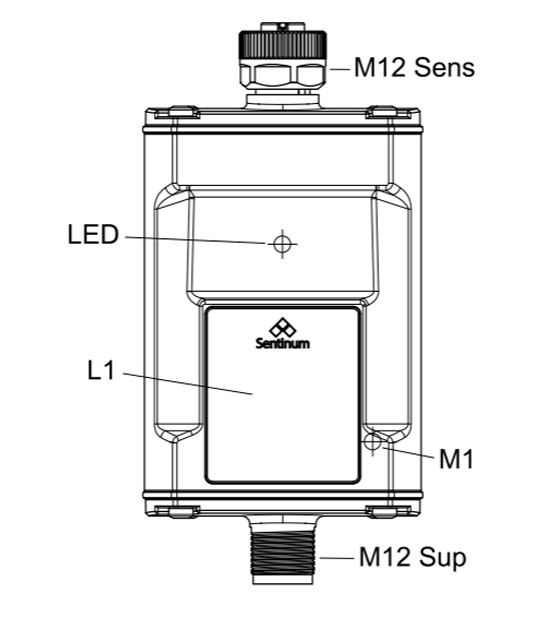
| Description | Description |
|---|---|
| M1 | Magnetic Switch 1 |
| M12 Sup | M12 Connection (Supply Side) |
| LED | LED - visual feedback and flashing signal |
| M12 Sens | M12 connection, sensor side |
| L1 | Labeled |
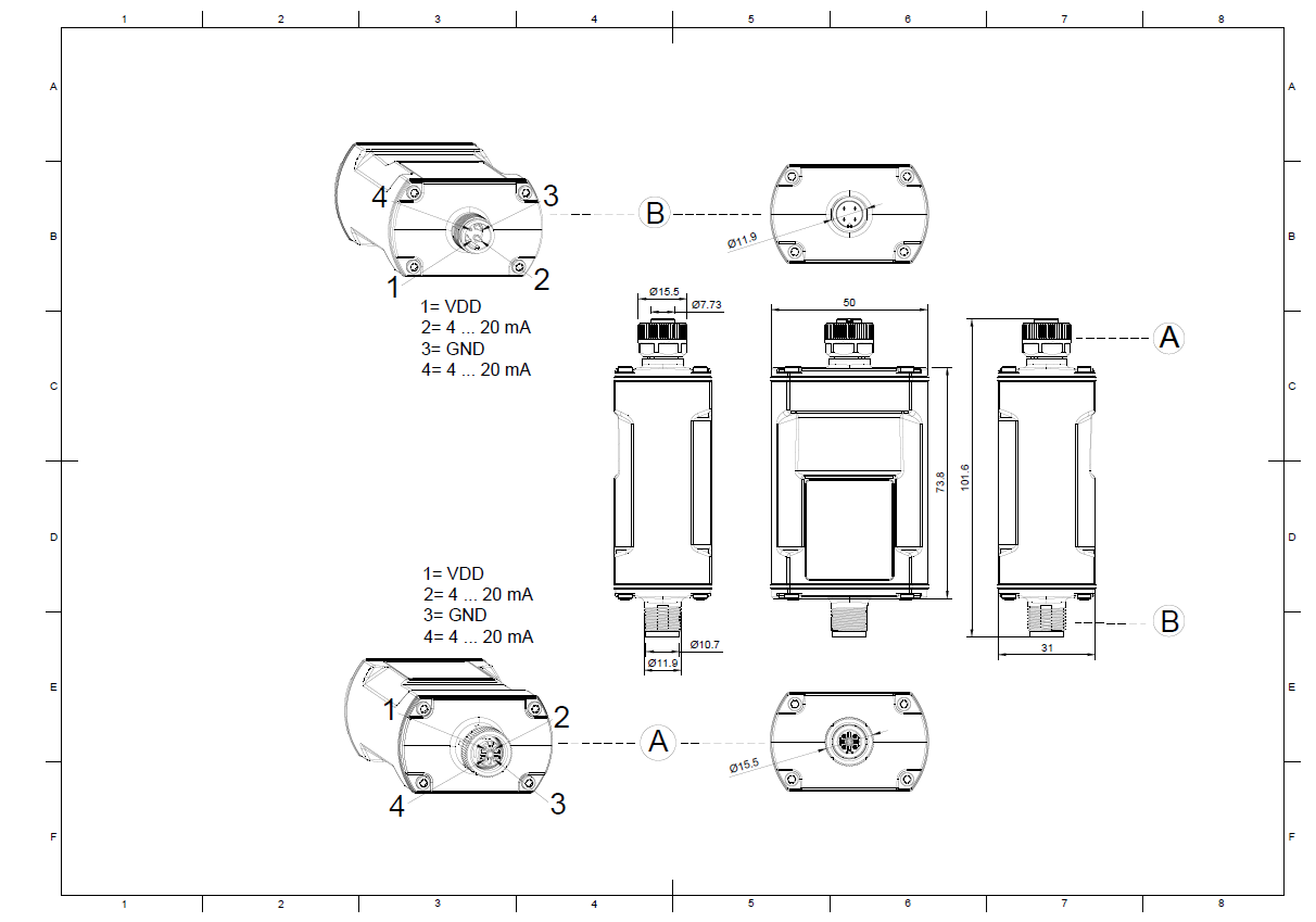
6.2. Connection Diagram and Pin Assignment (Sensor Side)
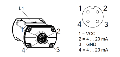
6.3. Connection Diagram and Pin Assignment (Supply Side) for the Terminated Version
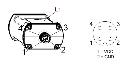
Pin configuration for direct connection of a 4–20 mA sensor. The device is powered via the supply connection by an external power supply and forms the end point of the measurement chain.
This version is not designed to pass on the 4–20 mA signal. The terminated version is particularly suitable for new installations or applications in which the sensor is detected exclusively by the AION420.
6.4. Connection Diagram and Pin Assignment (Supply Side) for the Looped Version
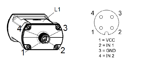
In addition to providing power, the looped version of the AION420 also allows the 4–20 mA signal to pass through. This enables the AION420 to be integrated into existing measurement circuits without interfering with the existing signal processing.
The measurement signal is acquired by the device and simultaneously transmitted to downstream systems, such as PLCs, data loggers, or process control systems.
This version is particularly suitable for retrofits and applications in which the existing infrastructure is to continue to be used.
6.5. Warning and Safety Instructions for Installation
If the sensor remains easily accessible after installation, install the sensor first and activate it after installation.
If the sensor is no longer accessible after installation, activate the sensor first and then install it. Before proceeding with this type of installation, make sure that the surface to which the sensor is to be screwed is level; otherwise, the housing may be damaged.
Please note:
- Do not insert any objects or body parts into the openings of the sensor.
- Do not mount the sensor on the ceiling or floor.
- Do not mount the sensor at heights exceeding two meters.
- Install the sensor only indoors on a wall in a standard room at a height of 1.50 m to 1.80 m.
The standard versions of the AION sensor are designed for a wide range of industrial and logistics applications and feature robust housings with a high protection rating. During installation, the following points must be observed:
- Choose a mounting location that falls within the specified ambient temperatures and conditions (see technical specifications).
- Do not cover the housing: Wireless communication (e.g., LoRaWAN, BLE) must not be obstructed by metallic objects, sealed housings, or structurally shielding materials.
- Securely mount the sensor, ideally using the provided mounting holes. Low-vibration or solid surfaces are recommended.
- Orientation: The standard version does not require any special orientation and can therefore be mounted flat, vertically, or horizontally, depending on the application.
- Do not mount in the immediate vicinity of strong electromagnetic sources to avoid signal interference.
Permanent magnets can generate strong magnetic fields that may be dangerous if handled improperly. Therefore, please observe the following warnings:
- Protect your hands and fingers: Strong magnets can suddenly attract each other and pinch fingers or skin. This can lead to painful bruises and injuries. Always maintain a safe distance when handling permanent magnets and wear protective gloves if necessary. Keep electronic devices away: Magnetic fields can damage electronic devices such as computers, smartphones, credit cards, pacemakers, and other sensitive electronics, or impair their function.
- Keep electronic devices away: Magnetic fields can damage electronic devices such as computers, smartphones, credit cards, pacemakers, and other sensitive electronics, or interfere with their operation. Therefore, always maintain a sufficient distance from such devices.
- Be aware of the risk of breakage: Many permanent magnets are made of brittle materials (e.g., neodymium) that can break if subjected to sudden impacts or excessive stress. The shards can be sharp and cause injuries. Therefore, handle the magnets with care and avoid impacts or excessive stress.
- Health Risks: People with pacemakers or other implanted medical devices should avoid contact with strong magnets, as the magnetic fields can interfere with or deactivate these devices. Consult a doctor before use if necessary.
- Store magnets safely: Keep magnets at a safe distance from each other and from other metallic objects. Sudden attraction can lead to damage, injury, or objects flying around uncontrollably.
- Danger to children: Permanent magnets are not toys. Small magnets in particular can be life-threatening if swallowed or inhaled and can cause serious internal injuries. Therefore, always keep magnets out of the reach of children.
- Avoid overheating: Permanent magnets permanently lose their magnetic strength at temperatures above their maximum operating temperature (between 80 and 200 °C, depending on the material). Therefore, do not expose magnets to direct heat or open flames.
6.6. Recommended Mounting Methods
| Installation Type | Description | Recommended Accessories |
|---|---|---|
| Mounting clip | Aluminum mounting clip | E89209, Z-AION420-CLIP |
6.7. Mounting Accessories
| Mounting Type | Recommended Accessories |
|---|---|
| Screw for mounting clip | M5 or M6 screw for mounting clip |
| Mounting clip | Aluminum mounting clip, Z-AION420-CLIP |
6.8. General Installation Instructions
Before installation, ensure that the intended mounting location is suitable for the device's operating conditions. The housing must be mounted in such a way that it is protected from mechanical damage, heavy contamination, and prolonged contact with water or corrosive media.
Before making any electrical connections, all circuits must be de-energized. The AION420 must be connected exclusively in accordance with the provided wiring diagram. Ensure correct polarity of the supply voltage and proper wiring of the 4–20 mA signal. Incorrectly connected wires or reversed polarities can lead to malfunctions or damage to the device and connected components.
The connection cables must be routed with strain relief and protected from mechanical stress. Cables must be routed so that they are not kinked, crushed, or excessively bent. Unused cable glands or connections must be sealed accordingly.
For optimal wireless communication, the sensor should be installed as far as possible from large metal surfaces, control cabinets, piping, or other objects that shield radio waves. The antenna must not be covered, kinked, or modified. For devices with an external antenna, follow the relevant installation instructions regarding antenna positioning.
After installation is complete, check all connections to ensure they are secure, correctly wired, and leak-free. Before commissioning, a functional test should be performed, including verification of the sensor signal and the radio connection.
The manufacturer recommends that maintenance and service work be performed exclusively by qualified technical personnel. Changes or modifications to the device that have not been expressly approved by the manufacturer may result in the loss of warranty and certification claims.
6.9. Wiring and Termination
For wiring the AION420, standard, field-terminable M12 connectors can be used on both the sensor side and the power supply side. These enable simple and flexible installation as well as quick replacement of connected components.
Alternatively, pre-assembled M12 connection cables with open cable ends can also be used. The open cable ends can be wired directly to the power supply or the 4–20 mA sensor to be connected, in accordance with the wiring diagram. In doing so, the respective wire assignments and correct polarity as shown in the wiring diagram must be observed.
It is recommended to use only connectors and connection cables suitable for industrial applications and to ensure that the connection elements are installed properly and are leak-tight. This ensures reliable operation of the system even under demanding environmental conditions.
6.10. Suspended Mounting
Due to its compact design, the AION420 can be installed directly between two M12 connection cables. To do this, the device is connected on one side to the power supply and on the other side to the 4–20 mA sensor to be connected. In many applications, suspended mounting is sufficient, with the device supported solely by the connected cables.
If environmental conditions or the installation require it, the sensor can also be secured against movement, vibration, or tensile stress. Suitable options include, for example, cable ties, adhesive tape, mounting clips, or similar fasteners. Care must be taken to ensure that the housing, the connection cables, and, if applicable, the antenna are not damaged or impaired in their function.
The connection cables must be routed so that no excessive tensile, compressive, or bending forces act on the connectors. Adequate strain relief increases operational safety and ensures a permanently reliable connection.
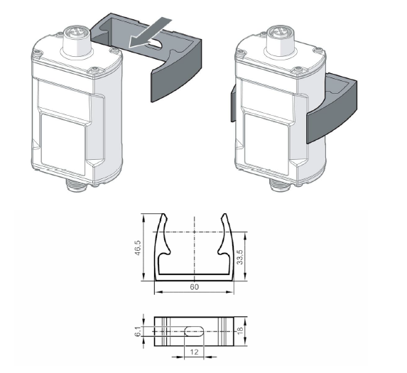
6.11. Mounting with a Mounting Clip
The AION420 can be mounted on solid surfaces such as walls, machine housings, control cabinets, or mounting panels using a suitable mounting clip. To do this, the mounting clip is attached to the desired mounting location using a screw through the existing mounting holes. The sensor is then pressed into the clip until it is securely held in place.
Mounting with a clip offers a simple and space-saving way to permanently secure the sensor while also protecting it from movement or tensile stress on the connection cables. For optimal accessibility, the M12 connectors and, if applicable, the antenna should remain freely accessible even after installation.
The connection cables must be routed so that no permanent tensile, compressive, or bending forces act on the connectors. If necessary, provide additional strain relief for the cables.
After installation, verify that the sensor is securely seated in the mounting clip and cannot come loose unintentionally. The mounting must be performed in such a way that reliable operation is ensured even under vibrations or normal mechanical stresses.
7. Commissioning and Configuration
Please note that using knives or other sharp objects may damage the housing or the electronics. There are two Hall sensors (magnetic switches) on the sensor. The following diagram shows the location of the Hall sensors and the recommended placement of the magnets.
| Designation | Description | Function |
|---|---|---|
| M1 | Magnetic Switch 1 |
|
| M2 | Magnetic switch 2 | Custom functions can be implemented |
7.1 Commissioning and Configuration of the Sensor via BLE
- All Eos variants can be activated via BLE using a cell phone. To do so, simply use our LinOs app from Sentinum GmbH, which you can find in the App Store or Google Play Store .
- Activate the sensor by briefly triggering the lower-left Hall sensor (M1) with a magnet for at least 2 seconds. The sensor should now emit a series of beeps. Advertising mode will then start automatically.
- You can now conveniently control the sensor via BLE from your device. Make sure that Bluetooth is turned on on your phone and that you are within range of the sensor to be able to connect to and control it.
Activate BLE Advertising
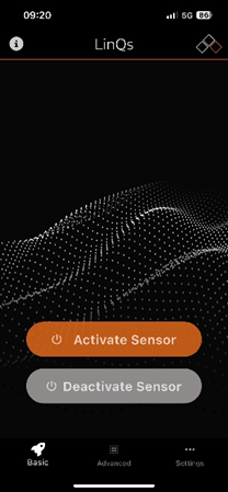
BLE Advertising mode can be activated using the magnets or after activating the sensor.
Search for a BLE device
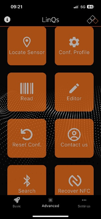
Use the "Search" button to search for the sensor via BLE.
Connect to the sensor via BLE
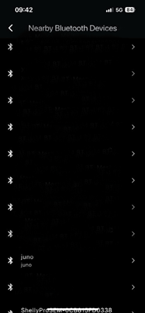
Select the correct sensor and confirm by clicking "Eos."
Connect to the sensor via BLE
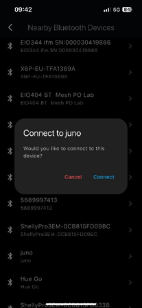
Click the "Connect" button
Configure the sensor via BLE
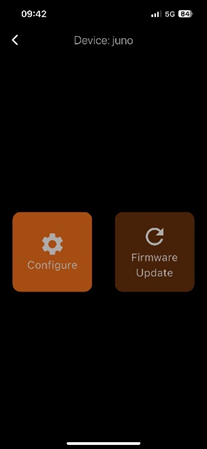
Now use the "Configure" button to set parameters.
Configure the sensor via BLE
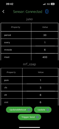
Use the "Trigger Send" button to initiate a transmission. Tap the desired table entry and change the values. Confirm by clicking the "Update & Reboot" or "Update" button at the bottom. "Update & Reboot" forces a reboot in addition to applying the changes; "Update" applies the changes during the next measurement or transmission.
7.2. Audible Signal and Flashing Pattern
- When the device is turned on, an audible signal sounds, consisting of several rising tones. This sequence of tones indicates that the sensor has been successfully activated.
- When the device is turned off, several descending tones are played, which acoustically confirm that the device is shutting down.
- When establishing or disconnecting a Bluetooth (BLE) connection, the sensor also emits an audible signal that confirms the connection status.
- There are also flashing codes, which are described in the following table .
8. Communication with the Interface
Detailed instructions for configuring sensor communication and join behavior can be found, depending on the version, in the respective generic LoRaWAN® , mioty® or Cellular (NB-IoT and LTE-M1) documentation.
Furthermore, you can find all documents related to the generic documentation at "https://docs.sentinum.de/wichtige-produktuebergreifende-dokumentation-fur-sensoren .
8.1. LoRaWAN Join Behavior
Before telemetry data can be sent via LoRaWAN, the device must establish a connection to the network. To do this, the device sends Join requests until a Join Accept is successfully received . As a compromise between power consumption and a quick Join, the transmission intervals between Join requests gradually increase. In addition, the data rate is varied (initially a high data rate or low spreading factor, then a lower data rate or higher spreading factor). The join behavior strictly adheres to the requirements and recommendations of the LoRa Alliance specification. Sentinum sensors implement these requirements using so-called join bursts, whose intervals between each burst increase.
A join burst consists of a maximum of 6 join requests with a decreasing data rate (DR5–DR0) or increasing spread factor (SF7–SF12). The intervals between requests increase quadratically to ensure compliance with the LoRa Alliance's specific duty cycle guidelines. The LoRa Alliance mandates a decreasing duty cycle for join requests according to the following table: Time Duty Cycle <1h 1% ~1h 0.1%
This means that in the first phase (<1h), exactly as much transmission budget is available as in the second phase (>1h), even though only one-tenth of the time is available. To maximize the use of the budget, the intervals between the join bursts (consisting of a maximum of 6 join requests) are initially short and then become longer. Specifically, two bursts are performed in Phase 1. In Phase 2, two additional bursts are performed, and starting in Phase 3, one burst is performed per day. The duration of the bursts increases from approximately 10 minutes in Phase 1 to approximately 100 minutes in Phase 2 and up to 16 hours in Phase 3.
8.2. mioty Join Behavior
Before telemetry data can be sent via mioty, the device must establish an initial communication link with the base station. An explicit join process, as required by LoRaWAN, is not necessary.
Instead, the device immediately begins transmitting so-called telegrams, which consist of 512-bit data packets that are in turn fragmented into up to 12 subpackets and distributed across different frequencies and time slots (telegram splitting).
The first successful delivery of a telegram with a valid device ID is interpreted by the backend as network joining. The device's configuration (e.g., device ID, application key) is predefined and must match the backend's settings.
If no confirmation is registered in the backend (e.g., due to missing reception timestamps or missing evaluation results), the device begins retrying the transmission. These retries occur in so-called mioty transmission cycles. The cycle duration increases progressively from an initial 5 minutes (after the first attempt), through 30 minutes, up to 12 hours, in order to comply with duty cycle specifications (< 1%) while minimizing energy consumption.
The transmission frequencies (868.0–868.6 MHz in Europe) and channels are cyclically switched to avoid multiple collisions. The device does not actively change the data rate, as this is defined by the protocol (15.625 kbit/s for the uplink, optionally 4.882 kbit/s for the downlink). The telegrams are robust against interference, since only 3 out of 12 subpackets need to be received correctly (Forward Error Correction).
A complete transmission attempt consists of a telegram with 12 subpackets lasting approximately 1.2 seconds (including guard time). Upon successful registration, the device switches to a regular operating mode with fixed transmission intervals. If no reception occurs after several transmission cycles (typically 10–12), the device pauses for 24 hours before a new initialization attempt is initiated.
9. Maintenance and Cleaning
To ensure that the sensor functions reliably and has a long service life, it should be maintained regularly. Please observe the following instructions:
- Clean the housing, especially the ventilation slots of the sensor, with a dry or slightly damp microfiber cloth. Make sure that no moisture enters the device.
- Clean the sensor regularly, especially in dusty or pollen-laden environments, to ensure the sensor's long-term functionality.
- Do not use cleaning agents containing alcohol or solvents, as these can damage the sensor's surface. Do not use compressed air or other aggressive
- Do not use compressed air or other aggressive cleaning methods, as these can damage sensitive sensor components .
- Hard deposits (e.g., limescale, oil, or grease) can impair measurement accuracy. If necessary, clean the sensor promptly using a soft, damp cloth and a mild detergent. For
- For optical or radar-based sensors, the lenses or antenna surfaces should be checked regularly for dirt or scratches.
- Regularly check that the sensor and its mounting are securely fastened.
Labeling and Certification