![Logo_quer_farbig.png]](https://docs.sentinum.de/hs-fs/hubfs/Logo_quer_farbig.png?height=40&name=Logo_quer_farbig.png)
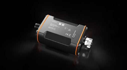
The AION420 is a compact IoT bridge for wirelessly connecting industrial 4–20 mA sensors to LoRaWAN® and mioty® networks. The device acquires analog process values and transmits the measured values energy-efficiently to existing IoT platforms without requiring additional cabling or local infrastructure.
Since the AION420 is part of the 4–20 mA current loop, the device is powered by an external power supply. This makes it particularly suitable for applications with an existing power supply and provides a reliable connection of existing measurement points to modern IoT infrastructures.
For easy integration into various systems, the AION420 is available both as a terminated version for direct connection to a sensor and as a loop-through version for integration into existing sensor cabling .
This allows existing 4–20 mA sensors to be digitized quickly and cost-effectively .
Typical applications include the monitoring of levels, pressures, flow rates, temperatures, and other process variables in industrial, energy, water, and environmental applications.
- Versions
- General Features
- Connectivity and RF Specifications
- Sensor Specifications: 4–20 mA Interface
-
Temperature Specifications
- Connections
- Electrical Parameters
-
Installation, Assembly, and Wiring
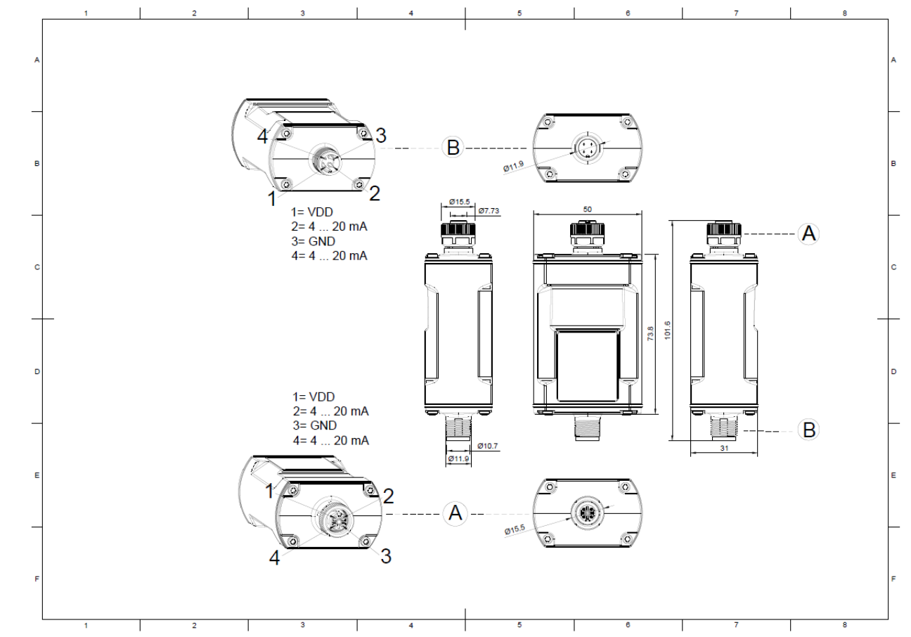
- Wiring Diagram and Pin Assignment (Sensor Side)
- Connection Diagram and Pin Assignment for the Supply Side of the Terminated Version
- Connection Diagram and Pin Assignment (Supply Side) for the Looped Version
1. Versions
| Part Number | Class | Version | Configuration | Interface |
|---|---|---|---|---|
| S-AION-LOEU-420 | LoRaWAN Class A | Terminated | BLE | 4-20 mA (2 channels) |
| S-AION-MIOTY-420 | mioty Class A | Terminated | BLE | 4–20 mA (2 channels) |
| S-AION-LOEU-420-3L | LoRaWAN Class A | Loop | BLE | 4–20 mA (2 channels) |
| S-AION-MIOTY-420-3L | mioty Class A | Loop | BLE | 4–20 mA (2 channels) |
2. General Features
| Feature | Value | Unit |
|---|---|---|
| Dimensions (D x H) | 99.1 x 50 x 31 | mm |
| Weight | 130 | g |
| Operating temperature | -20 to 80 | °C |
| Storage temperature (recommended) | 15 to 25 | °C |
| Relative humidity during operation | 10 to 90 | % |
| IP Rating | IP67/IP65 | |
| Traffic light function / Visual feedback | LED | |
| Acoustic alarm function | Buzzer | |
| Provisioning and Configuration | BLE | |
| Material | Housing: PA; Cover: PA; Cover gasket: TPE; M12 gasket: FKM | |
| BLE antenna | Integrated | |
| RF antenna | Integrated for all versions | |
| Accelerometer | Optional | |
| Batteries | None | |
| Primary cell type | - | |
| Outdoor use | No |
3. Connectivity and RF Specifications
| Feature | Value | Unit |
|---|---|---|
| RF standards | ||
| Frequency LoRaWAN® / mioty® EU | 868 | MHz |
| Transmit Power LoRaWAN® / mioty® EU | 14 | dBm |
| LoRa® MAC Layer Version | 1.0.4 |
4. Sensor Specifications: 4–20 mA Interface
| Characteristic | Value | Unit |
|---|---|---|
| Type Accuracy | Absolute Error 0.05 mA + Relative Error 0.25% |
5. Temperature Specifications
| Characteristic | Value | Unit |
|---|---|---|
| Temperature Range | -30 to +85 | °C |
| Accuracy 0°C to 70°C | ±2 | °C |
| Accuracy from -40°C to +85°C | ±1.5 | °C |
| Resolution | 1 | °C |
5.1 Connections
| Characteristic | Value | Unit |
|---|---|---|
| Sensor side | A-coded, female with cap nut | |
| Supply side |
A-coded, male
|
5.2 Electrical Parameters
| Characteristic | Value | Unit |
|---|---|---|
| Operating voltage | 9 to 26 | V |
| Rated voltage | 24 | V |
| Max. Current Consumption | 0.2 | A |
| Max. Current Carrying Capacity | 0.3 | A |
6. Installation, Assembly, and Wiring
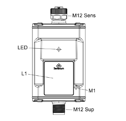
| Component | Description |
|---|---|
| M1 | Magnetic Switch 1 |
| M12 Sup | M12 connection, supply side |
| LED | LED – visual feedback and flashing signal |
| M12 Sens | M12 Sensor-Side Connection |
| L1 | Labeled |
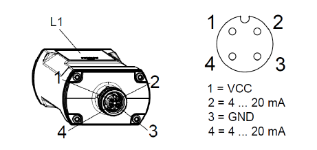
6.1 Wiring Diagram and Pin Assignment (Sensor Side)
6.2 Connection Diagram and Pin Assignment for the Supply Side of the Terminated Version
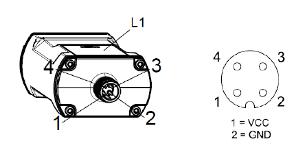
Pin configuration for direct connection of a 4–20 mA sensor. The device is powered via the supply connection by an external power supply and forms the end point of the measurement chain.
This version is not designed to pass on the 4–20 mA signal . The terminated version is particularly suitable for new installations or applications in which the sensor is detected exclusively by the AION420.
6.3 Connection Schematic and Pin Assignment (Supply Side) for the Looped Version
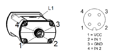
In addition to providing power, the looped-through version of the AION420 also allows the 4–20 mA signal to pass through. This enables the AION420 to be integrated into existing measurement circuits without interfering with the existing signal processing.
The measurement signal is acquired by the device and simultaneously forwarded to downstream systems, such as PLCs, data loggers, or process control systems.
This design is particularly suitable for retrofits and applications where the existing infrastructure is to continue to be used.