![Logo_quer_farbig.png]](https://docs.sentinum.de/hs-fs/hubfs/Logo_quer_farbig.png?height=40&name=Logo_quer_farbig.png)
- Symbols and Explanations
- Safety Instructions
- Technical Drawing
- Installation and Preparation
- Installation Accessories
- Recommended Installation Methods
- NFC Setup and Location of the NFC Tag
- Setup Without a Mobile Device
- Battery Replacement
1. Symbols and Explanations
Warnings and important information about potential hazards or possible damage.
Important information required for the smooth operation of the devices .
2. Safety Instructions
- Follow the safety instructions and installation guidelines in the manual and the installation checklist.
- Ensure that the installation environment complies with the specified operating environment guidelines. Always adhere to temperature and other limits.
- The device may only be used within the ranges specified in the technical specifications.
- The device may only be used for the intended purpose described.
- Safety and functionality can no longer be guaranteed if the device is modified or expanded.
- It may not function properly.
- It may be permanently damaged.
- It may pose a risk of injury.
- Improper handling, such as subjecting the device to excessive mechanical stress or dropping it, can result in damage.
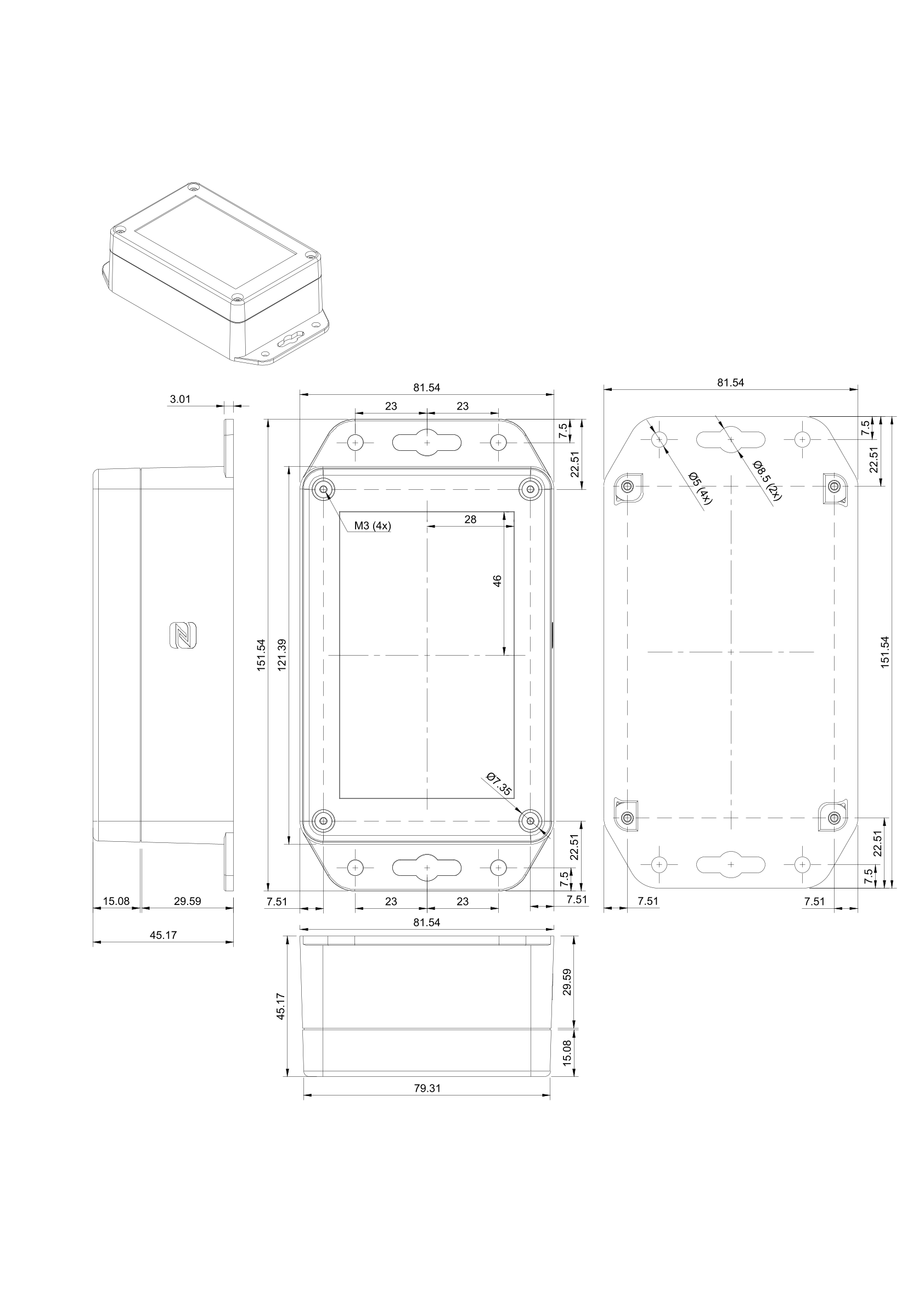
3. Technical Drawing
4. Installation and Preparation
If the sensor remains easily accessible even after installation, install the sensor first and activate it only after installation.
If the sensor is no longer accessible after installation, activate the sensor first and then install it afterward.
- If you have ordered a device with an external antenna, which can be identified by the gold-colored RP-SMA connector, first install the antenna included in the package.
-
The sensor can be mounted either horizontally or vertically
. For wall or magnetic mounting, use the
mounting holes provided in the side tabs
of the housing.
.png?width=688&height=384&name=Untitled%20(32).png)
Figure 3. Possible sensor mounting positions - Depending on the sensor model and variant, the antenna and sensor connections may be located on the long or short side of the housing.
External antenna: Please note that the antenna must always must be mounted vertically and its tip must point toward the ceiling. Tilt the antenna at the joint so that it is always aligned vertically. The external antenna is usually located on the long side of the housing. The antenna should maintain a minimum distance of 2 cm from metal surfaces. Make sure that the antenna is not shielded by surrounding metal parts, provided that the application allows it.
Internal Antenna: If your device has an internal antenna (no external antenna visible), the Helios sensor must always be mounted with the long side oriented vertically, as this ensures maximum signal strength. The antenna is located on the underside (opposite the logo side) of the housing and should also be kept at least 2 cm away from metal surfaces. Make sure the antenna is not shielded by surrounding metal parts, as long as the application permits.
If you have a device with an external antenna, the device must never be operated without the antenna connected. Otherwise, the sensor may be irreparably damaged.
5. Mounting Accessories
| Part Number | Recommended Accessories |
|---|---|
| Z-MAG-NEO-M4 | 2 neodymium pot magnets, holding force 32 kg, incl. 2 screws |
| Z-HS-4 | Pair of 4 mm wood screws with anchors |
| Z-HS-5 | Pair of 5 mm wood screws with anchors |
6. Recommended Installation Methods
| Type | Recommended Accessories | Sentinum Part Number | Manufacturer |
|---|---|---|---|
| Screws (wall) |
DIN 912 cylinder head screws or wood screws, depending
material, with anchors.
Permissible sizes:
|
- | - |
| Magnets | Neodymium magnets, M4 internal thread | - | - |
| Adhesive | Double-sided adhesive tape | - | - |
7. NFC Setup and Location of the NFC Tag
You can use the LinQs NFC app to configure parameters . Please make sure you know where the NFC reader on your mobile device is located. Depending on the manufacturer and model, it may be located at the top, middle, or bottom of the device's back. To locate the NFC tag, select "Read" in the app, for example, and slowly move the smartphone along the sensor.
- Activation is performed via an NFC app. This requires a smartphone. The app can be downloaded from the respective app stores . Simply search for Sentinum LinQs and download the app.
-
First, locate the NFC tag on the sensor, and
then locate the NFC reader on your device. The position
of the NFC tag is shown in the following figure.
.png?width=688&height=387&name=Helios%206%20(1)%20.png)
Figure 5. Position of the NFC tag on the Helios-P sensor -
Open the app and activate the sensor. To start the sensor
with the default settings, select the
Activate Sensorbutton in the app's start menu. Then place your device on the sensor's NFC tag..png?width=688&height=275&name=Untitled%20(26).png)
Figure 6. Activating the sensor via the LinQs app If the sensor is successfully activated, the message
Sensor Updated!appears. Afterward, additional sensors can be activated.
.png?width=2064&height=993&name=Untitled%20(24).png)
8. Setup Without a Mobile Device
If you do not have a smartphone on hand, you can
restart the sensor directly on the device. To do this, slide the marked
switch to the Off position, wait at least
10 seconds, and then slide it back to the
On position. The sensor will then restart and
resume normal operation, such as the
LoRaWAN® join procedure.
.png?width=688&height=392&name=Untitledazy)
9. Battery Replacement
-
Open the housing with a suitable
Phillips screwdriver. Carefully remove the cover
and be careful not to damage the gasket.
.png?width=688&height=512&name=Untitled%20(34).png)
Figure 8. Opening the sensor housing -
Before replacing the battery, turn off the sensor by flipping
the switch to the
Offposition..png?width=688&height=392&name=Untitled)
Figure 9. Turning off the sensor before replacing the batteries Then carefully remove the batteries from the designated holder and insert new batteries.
To achieve the specified runtime and performance, the following primary cells are approved:
- Energizer® Ultimate Lithium AA
- VARTA ULTRA LITHIUM Mignon AA
- Dispose of the old batteries properly after replacement . Then close the housing again and make sure the seal is correctly seated in its original position.
If battery types other than those recommended are used, performance, runtime, and product safety may be compromised .