1. Version History
| Version | Date | Revision |
|---|---|---|
| 1.0.0 | June 2, 2025 | Created |
| 1.0.1 | March 25, 2026 |
|
2. Overview
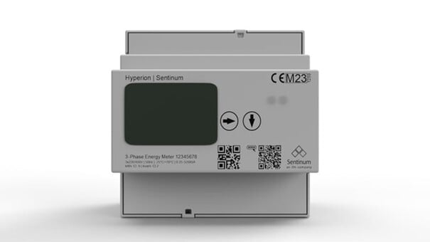
The Hyperion energy meter is a device from Sentinum that transmits energy measurement data via the MIOTY communication protocol. This document describes the payload structure, available profiles, and field definitions for firmware version 1.3 and higher.
Device Information:
- EUI Type:
FCA84A0000000006 - Manufacturer: Sentinum
- Protocol: MIOTY
- Supported version: 1.3+
3. Payload Structure
Header (same for all profiles)
Every Hyperion payload begins with a common header structure:
| Field | Size | Type | Description |
|---|---|---|---|
FW_BASE_ID |
4 bits | Uint | Firmware base identifier |
FW_MAJOR_VER |
4 bits | Uint | Major version of the firmware |
FW_MINOR_VER |
4 bits | Uint | Firmware minor version |
DEV_SUB_TYPE |
4 bits | Uint | Device subtype identifier |
MSG_COUNTER |
8 bits | Uint | Counter for uplink messages |
STATUS |
8 bits | Uint | Device status (0 = Normal operation) |
SERIAL_NUM |
32-bit | Uint | Visible serial number of the device |
APP_VERSION |
32-bit | Uint | Visible application version |
MID_VERSION |
32-bit | Uint | Visible middleware version |
PROFIL |
32-bit | Uint | Payload profile selector (0-4) |
Payload Requirements:
- Payload data is only transmitted if
fw_minor_ver >= 3andstatus == 0. - The profile selection is controlled via the profile field.
4. Payload Profiles
The payload profiles are described below.
4.1. Profile 0: Complete Energy Data (Big Endian)
Purpose: Comprehensive electrical measurements, including power, current, voltage, energy meters, and power quality parameters.
Parameters:
Power measurements (W):
p_l1_a,p_l2_a,p_l3_a: Active power per phasep_l123_a: Total active power (sum of all phases)
Current measurements (mA):
i_l1,i_l2,i_l3: Current per phasei_l123: Total current
Voltage measurements (V, scaled by /10):
u_l1,u_l2,u_l3: Phase voltagesu_l12,u_l23,u_l31: Line-to-line voltages
Energy meter (Wh):
e_ta_a_i: Total active energy importe_ta_a_e: Total active energy exporte_ta_r_i: Total reactive energy importe_ta_r_e: Total reactive energy export
Power quality:
pf_l1,pf_l2,pf_l3: Power factor per phase (scaled by /100)f: Frequency in Hz (scaled by /10)
System status:
pwr_fail: Power failure counter
4.2. Profile 1: Focus on voltage and current (Big Endian)
Purpose: Detailed voltage and current measurements with power quality metrics.
Fields:
Voltage measurements (V, scaled by /10):
u_l1,u_l2,u_l3: Phase voltagesu_l12,u_l23,u_l31: Line voltages
Current measurements (mA):
i_l1,i_l2,i_l3: Current per phasei_l123: Total current
Line quality:
pf_l1,pf_l2,pf_l3: Power factor per phase (scaled by /100)f: Frequency in Hz (scaled by /10)
4.3. Profile 2: Power and Current Analysis (Big Endian)
Purpose: Focuses on power measurements and current analysis with power quality.
Fields:
Power measurements (W):
p_l1_a,p_l2_a,p_l3_a: Active power per phasep_l123_a: Total active power
Current measurements (mA):
i_l1,i_l2,i_l3: Current per phasei_l123: Total current
Line quality:
pf_l1,pf_l2,pf_l3: Power factor per phase (scaled by /100)f: Frequency in Hz (scaled by /10)
4.4. Profile 3: Energy Meter Only (Big Endian)
Purpose: Energy accumulation data for billing and monitoring applications.
Fields:
Energy meter (Wh):
e_ta_a_i: Total active energy importe_ta_a_e: Total active energy exporte_ta_r_i: Total imported reactive powere_ta_r_e: Total reactive energy export
4.5. Profile 4: Extended Historical Data (Little Endian)
Purpose: Comprehensive historical data with time-based energy records and configuration parameters.
Fields:
Time and Index
- Index: Data set index
- epoch: Current timestamp
- epoch_old: Previous timestamp
Time-based energy meters
Tariff 1 (T1)
e_t1_a_i: Active energy importe_t1_a_e: Active energy exporte_t1_r_i: Reactive power importe_t1_r_e: Reactive power feed-in
Rate 2 (T2)
e_t2_a_i: Active energy importe_t2_a_e: Active energy exporte_t2_r_i: Reactive energy importe_t2_r_e: Reactive energy export
Current measurements (mA)
i_l1,i_l2,i_l3: Current per phasei_l4: Additional current measurementi_l123: Total current
Power measurements (W)
p_l1_a,p_l2_a,p_l3_a: Active power per phasep_l123_a: Total active powerp_l123_a_avg: Average total active power
Voltage measurements (V, scaled by ÷10)
u_l1,u_l2,u_l3: Phase voltages
Line quality
f: Frequency in Hz (scaled by ÷10)pf_l1,pf_l2,pf_l3: Power factor per phase (scaled by ÷10)
Transformer configuration
ct_act_prim: Actual primary ratio of the current transformerct_old_prim: Current transformer old primary ratioct_act_sec: Current transformer actual secondary ratioct_old_sec: Current transformer old secondary ratiovt_act_prim: Voltage transformer – actual primary ratiovt_old_prim: Voltage transformer – old primary ratiovt_act_sec: Voltage transformer – actual secondary ratiovt_old_sec: Voltage transformer – old secondary ratio
5. Data decoding
Endianness
- Profiles 0–3: Big-endian encoding
- Profile 4: Little-endian encoding
Data types and scaling
| Component | Size | Type | Scale | Unit | Description |
|---|---|---|---|---|---|
VOLTAGE_* |
32-bit | int | ÷10 | V | Voltage measurements |
CURRENT_* |
32-bit | int | 1:1 | mA | Current measurements |
POWER_* |
32-bit | int | 1:1 | W | Power measurements |
ENERGY_* |
64-bit | uint | 1:1 | Wh | Energy accumulation |
| POWER FACTOR | 8-bit | int | ÷100 (÷10 for LE) | - | Power factor (-1.0 to 1.0) |
| FREQUENCY | 16-bit | int | ÷10 | Hz | Mains frequency |
| EPOCH | 64-bit | uint | 1:1 | seconds | Unix timestamp |
CT_* / VT_* |
16-bit | uint | 1:1 | - | Transformer ratios |
Field Naming Convention
- Voltage:
u_lX(X = phase number or line designation) - Current:
i_lX(X = phase number or total) - Power:
p_lX_a(active power, X = phase or total) - Energy:
e_tX_Y_Zwhere: - t = Tariff (ta = Total, t1 / t2 = Tariff 1 / 2)
- Y = Energy type (a = Active power, r = Reactive power)
- Z = Direction (i = Import, e = Export)
- Power factor:
pf_lX(X = number of phases) - Frequency:
f - Transformer ratios:
ct_*= current transformer,vt_*= voltage transformer - Format:
{ct|vt}_{act|old}_{prim|sec}for actual/old primary/secondary values
6. Application Examples
- Profile 0: Used for comprehensive monitoring where all parameters are required
- Profile 1: Used for power quality analysis and load monitoring
- Profile 2: Used for power analysis and load monitoring
- Profile 3: Used for billing applications where only total energy values are required
- Profile 4: Used for historical data collection and advanced analysis
7. Data Interpretation
// Example: Converting voltage reading
const voltage_raw = 2350; // Raw value from u_l1
const voltage_actual = voltage_raw / 10; // = 235.0 V

// Example: Converting power factor
const pf_raw = -85; // Raw value from pf_l1 (big-endian profiles)
const pf_actual = pf_raw / 100; // = -0.85 (capacitive load)

// Example: Energy consumption calculation
const energy_import = e_ta_a_i; // in Wh
const energy_export = e_ta_a_e; // in Wh
const net_consumption = energy_import - energy_export; // Net energy

// Example: Transformer ratio interpretation
const ct_primary = ct_act_prim; // Current transformer primary ratio
const ct_secondary = ct_act_sec; // Current transformer secondary ratio
const ct_ratio = ct_primary / ct_secondary; // Actual CT ratio
8. Version Compatibility
This design supports Hyperion firmware version 1.3 and higher.
The payload structure depends on the following factors:
fw_minor_ver >= 3: Required for the transmission of payload datastatus == 0: Normal operating status; payload data required
For versions prior to 1.3, only header information is available.
9. Technical Notes
- No hidden fields: All data fields are visible and accessible in the decoded payload.
- Visible components: Serial numbers, version information, and CT/VT ratios are all visible.
- Conditional logic: All payload fields are dependent on version, status, and profile selection.
- Data validation: Ensure correct endianness handling when implementing decoders.
- Profile optimization: Different profiles optimize payload size for specific use cases.
- Time-based data: Profile 4 contains historical data with epoch timestamps for time series analysis.
- Transformer ratios: CT/VT ratios are transmitted as 16-bit values representing the transformer configuration.
- Optimized design: Optimized component definitions eliminate unnecessary complexity while ensuring full functionality.