- 1. Version History
- 2. General Warnings and Safety Instructions
- 3. Additional Documentation
- 4. Intended Use and Product Versions
- 4.1 Product Codes and Functions
- 4.2 Intended Use
- 4.3 Differences Between iX Versions
- 5. Technical Drawing
- 5.1 Juno TH (with TH opening)
- 6. Scope of Delivery
- 6.1 Technical drawing of adhesive pad
- 7. Approved Batteries and Types
- 8. Accessories
- 9. General Handling Instructions
- 9.1 Special handling instructions for -TH versions
- 10. Assembly and Installation
- 10.1 Warning and safety instructions for assembly
- 10.2 Recommended Mounting Methods
- 10.3 General Installation Instructions
- 10.4 Installation instructions for Juno TH versions
- 10.5 Additional Assembly Instructions for Optimal Range
- 10.6 Wall mounting with screws
- 10.7 Wall mounting with magnets
- 10.8 Wall mounting with adhesive strips
- 11. Commissioning and Use
- 11.1 Commissioning the sensor with a magnet
- 11.2 Setting up the sensor via NFC
- 11.3 Audible signal and feedback
- 12. Sensor Functions
- 12.1 Hysteresis
- 12.2 Inclination and Tilt Detection
- 13. Maintenance and Cleaning
- 14. Battery Replacement
- 15. Flap opening detection and tilt detection
- 15.1 Flap opening detection via the magnetic switch
- 15.2 Flap opening detection using an accelerometer and tilt detection
- 15.3 Orientations
- 16. Marking and certification
1. Version History
| Version | Date | Revision |
|---|---|---|
| 1.0.0 | April 30, 2026 | Created |
2. General Warnings and Safety Instructions
Warnings and important information about potential hazards or damage.
Important instructions necessary for the smooth operation of the devices.
Please note:
- Follow the safety instructions and installation guidelines in the manual and the installation checklist.
- Ensure that the installation environment complies with the specified operating range guidelines. Always adhere to temperature and other limit values.
- The device may only be used within the ranges specified in the technical specifications.
- The device may only be used for the described purposes and in the specified areas.
- Safety and functionality can no longer be guaranteed if the device is modified or expanded.
- The sensor must not be mounted on ceilings or floors.
- Operation of the sensor is only permitted up to a maximum of 2,000 meters above sea level.
- Operation is only permitted in rooms with a ceiling height of up to 2 meters.
- Due to human exposure regulations, a minimum distance of 20 cm between the device and people must be maintained.
- Ensure that the installation environment complies with the prescribed guidelines for the intended use. Adhere to the temperature and other limit values at all times.
If the device is installed incorrectly:
- It may not function properly.
- It could be permanently damaged.
- It could pose a risk of injury.
Please note:
- Improper handling, such as excessive mechanical stress (e.g., dropping the device), may cause damage.
- Using battery cells other than those recommended may negatively affect performance and product safety.
- The device may only be installed and put into operation if it can be removed from the original packaging undamaged. A visual inspection for damage must be performed immediately after removal. If the product is damaged, it must not be put into operation.
3. Additional Documentation
Please refer to the information and limit values in the technical data sheet.
The sensor-specific factory settings, configuration options, keys, and permissible values for the sensor can be found in the NFC and downlink description.
Depending on the version, you can find instructions for configuring sensor communication in the corresponding generic mioty® documentation.
All documents related to the generic documentation can be found at https://docs.sentinum.de/wichtig-produktübergreifende-dokumentation-für-sensoren.
4. Intended Use and Product Versions
This operating manual applies to the entire Juno product series.
Within the series, there are various product versions that differ in their positioning methods as well as in the features and functionality of the sensor technology. The specific characteristics and functions of the respective versions are explained separately later in this manual.
4.1 Product Codes and Functions
| ITEM CODE | IFM ITEM CODE | FEATURES |
|---|---|---|
| S-JUNO-IX-MIOTY-TH | ZJF 201 | INDUSTRIAL JUNO IP67 TH Sensor, Temperature and Relative Humidity with Tilt Detection and Door Open Detection mioty |
4.2 Intended Use
The Juno sensor is a wireless, battery-powered IoT device for recording temperature and relative humidity data. It is designed for use in industrial and commercial applications, particularly for condition monitoring and object localization in indoor and outdoor areas.
Depending on the product variant, the sensor features different sensor modules (e.g., temperature, motion, tilt). The sensor is intended exclusively for the applications described in the manual and may only be operated within the technical specifications stated therein.
Any other use or use beyond these specifications is considered improper. Sentinum GmbH assumes no liability for any resulting damage.
4.3 Differences Between iX Versions
The Juno iX versions feature extended certifications for industrial use.
In addition, they offer an expanded scope of delivery as well as additional configuration options regarding measurement and transmission intervals. For example, the iX models allow for a minimum measurement and transmission interval of one minute, whereas the standard version requires a minimum interval of five minutes. The industrial Juno versions and the standard versions also differ in their housing color.
| Version | Housing Color |
|---|---|
| -iX industrial versions | Light gray |
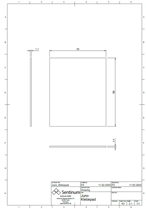
5. Technical drawing
5.1 Juno TH (with TH opening)
Technical drawing showing the opening for the TH sensor.
2.webp)
6. Scope of Delivery
| Product versions | Scope of delivery |
|---|---|
| -iX industrial versions | Sensor Battery Adhesive pad |
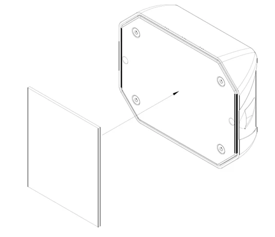
6.1 Technical drawing of adhesive pad
7. Approved Batteries and Types
The following battery types are approved for use with this product.
Please note that the choice of battery has a significant impact on runtime.
For maximum operating time, we recommend using the standard batteries.
| Part number | Approved batteries |
|---|---|
| S-JUNO(-iX)-MIOTY | Energizer Ultimate Lithium AA Varta ULTRA Lithium AA Varta Longlife Power AA SAFT LS14500 (Standard) |
8. Accessories
| Item Number | Description |
|---|---|
| PBA-000102 | Adhesive pad for Juno |
| Z-JUNO-MAG-NEO | 2x neodymium magnets with screws for Juno series sensors, holds 36 kg. |
9. General Handling Instructions
- Transport and Storage
Transport and store the sensor in its original packaging to prevent mechanical damage and static discharge.
Store the device according to the parameters specified in the technical data sheet. - Installation
Use only the designated mounting points on the housing for fastening.
Ensure that the sensor is mounted securely and vibration-free to avoid compromising measurement accuracy. - Commissioning
Ensure that the battery is inserted correctly and has sufficient charge.
Activate the sensor using the built-in magnetic switch or the provided smartphone app (depending on the model).
Use the software or app provided by Sentinum for configuration. - Operation
Operate the sensor exclusively within the specified environmental conditions (temperature, humidity, protection class).
Avoid strong magnetic fields or metallic shielding that could interfere with wireless communication or sensor functions. - Cleaning
Clean the housing as needed with a slightly damp, lint-free cloth.
Do not use aggressive cleaning agents or solvents.
The Tracker versions (non-TH, without opening) are IP69k-rated and can be cleaned accordingly. - Maintenance
The Juno sensor requires minimal maintenance. Depending on usage, the battery will need to be replaced after several years.
Regularly check the function and the connection to the backend system. - Disposal
Dispose of the device at the end of its service life in accordance with local regulations for the return of electronics and batteries.
9.1 Special handling instructions for -TH versions
The Juno TH versions are equipped with a special membrane to facilitate air exchange, ensuring precise temperature and humidity measurements.
Please observe the following instructions when handling the membrane:
- The membrane is sensitive to mechanical stress. Do not insert any pointed or sharp objects into the opening.
- Contamination from chips, dust, or particles must be strictly avoided. Ensure that the membrane does not become clogged. This impairs measurement accuracy.
- Do not clean or replace the membrane yourself. Always contact the manufacturer or authorized service centers for this.
- The membrane must not come into contact with aggressive cleaning agents. This can permanently damage the membrane or alter its permeability.
Installation Note:
- Even though the sensor has an IP67 protection rating, water must not accumulate in the area of the membrane opening. Standing water can lead to inaccurate measurements.
- For outdoor use, the sensor must always be mounted at an angle of at least 45° so that the membrane faces downward.
- Do not position the sensor close to the ground or in areas subject to splashing water to prevent dirt, mud, or standing water from entering the opening.
Improper handling can lead to measurement errors or malfunctions.
Additionally:
- Ensure air circulation: The sensor should not be mounted in completely enclosed housings or heavily shielded areas. Free air circulation is essential for accurate humidity and temperature measurements.
- Avoid UV exposure: Prolonged direct sunlight can damage the housing material and potentially the membrane structure. Installation in a partially shaded area or under a small cover is recommended, provided that environmental conditions permit.
- Prevent condensation: In the event of significant temperature fluctuations, condensation may form around the diaphragm opening if the sensor is installed in an unfavorable position. This is another reason why installation at an angle, pointing downward, is crucial.
- Do not paint or coat: The housing, especially the diaphragm opening, must not be painted over, varnished, or coated. Even thin layers can block the diaphragm and lead to significant measurement errors.
- Do not use in aggressive atmospheres unless explicitly approved. Such conditions can damage the diaphragm and electronics.
10. Assembly and Installation
10.1 Warning and safety instructions for assembly
If the sensor remains easily accessible after installation, install the sensor first and activate it after installation.
If the sensor is no longer accessible after mounting, activate the sensor first and mount it after activation.
Before proceeding with this type of mounting, ensure that the surface to which the sensor is to be screwed is level, as otherwise the housing may be damaged.
Please note:
- Do not insert any objects or body parts into the sensor openings.
- Do not mount the sensor on the ceiling or floor.
- Do not install the sensor at heights exceeding two meters.
- Install the sensor only indoors on a wall in a standard room at a height of 1.50 m to 1.80 m.
Permanent magnets can generate strong magnetic fields that can be dangerous if handled improperly. Therefore, please observe the following warnings:
- Protect your hands and fingers: Strong magnets can snap together suddenly and trap fingers or skin.
- Keep electronic devices away: Magnetic fields can damage electronic devices such as computers, smartphones, credit cards, pacemakers, and other sensitive electronics, or interfere with their operation.
- Be aware of the risk of breakage: Many permanent magnets are made of brittle materials that can break if subjected to sudden impacts or excessive stress.
- Health risks: People with pacemakers or other implanted medical devices should avoid contact with strong magnets.
- Store magnets safely: Keep magnets at a safe distance from each other and from other metallic objects.
- Danger to children: Permanent magnets are not toys.
- Avoid heating: Permanent magnets permanently lose their magnetic force at temperatures above their maximum operating temperature.
10.2 Recommended Mounting Methods
| Mounting type | Description | Recommended accessories |
|---|---|---|
| Screw mounting | 2 M4 or M5 screws | 2x suitable countersunk screws, or 4 mm-5 mm wood screws if necessary |
| Magnets | 2 M4 neodymium pot magnets, female thread | 2x neodymium magnets (indoor) with a combined load capacity of 16-32 kg |
| Adhesives | Double-sided tape or mounting adhesive | Double-sided tape or mounting adhesive |
10.3 General Installation Instructions
Installation of Juno Tracker versions (without opening)
The standard versions of the Juno sensor are designed for a wide range of industrial and logistics applications and feature rugged housings with a high protection rating. The following points must be observed during installation:
- Select a mounting location that falls within the specified ambient temperatures and conditions.
- Do not cover the housing.
- Ideally, mount the sensor with a clear line of sight to the sky. This ensures smooth operation of the wireless interfaces.
- Securely mount the sensor, ideally using the provided mounting holes. Low-vibration or solid surfaces are recommended.
- Orientation: The standard version does not require special orientation and can therefore be mounted flat, vertically, or horizontally.
- Do not mount in the immediate vicinity of strong electromagnetic sources to avoid signal interference.
10.4 Installation instructions for Juno TH versions
The TH versions contain a sensitive air exchange membrane for precise climate monitoring. Therefore, additional requirements apply:
- Always mount the sensor in an inclined position of at least 45° so that the membrane faces downward.
- Do not install near the floor or in areas subject to splashing water.
- Select a mounting location that ensures free air circulation.
- Do not expose to direct sunlight to prevent overheating and measurement errors.
- Prevent particle or dust contamination and avoid installation in very dusty areas.
- The membrane must not be sealed, glued, or painted over.
- Cleaning or replacement of the membrane should only be performed by authorized service providers or in consultation with the manufacturer.
10.5 Additional Assembly Instructions for Optimal Range
To ensure the best possible performance, please observe the following installation instructions for the Tracker versions:
- The sensor should always be mounted outside of metal enclosures.
- Avoid installation in the immediate vicinity of metal surfaces or metallic structures.
- Maintain a minimum distance of 30 cm from metallic materials in front and to the side.
- Place the sensor away from high-voltage power lines and strong electromagnetic fields.
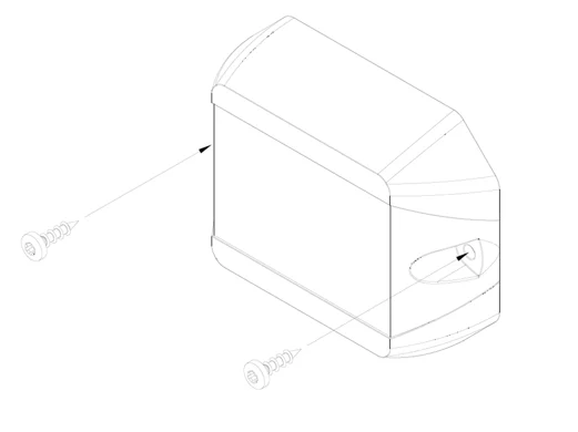
10.6 Wall mounting with screws
The Juno sensor can be securely and permanently mounted on a wall or other solid surface. Mounting is performed using the screw holes provided in the housing flange.
Preparing for installation
- Determine the mounting position: Select a mounting location that is low-vibration, dry, and suitable for sensor operation.
- Check the mounting surface: Solid surfaces such as concrete, masonry, wood, or engineering plastic panels are suitable. Use anchors suitable for porous surfaces.
- Prepare tools: cordless screwdriver or screwdriver with torque control, drill bit, anchors if needed, screws.
Screw selection
- The mounting holes in the sensor housing are designed for M4 screws.
- Depending on the mounting surface, the following are recommended: M4 cylinder head screws for plastic housings or metal frames, or Spax screws 4x35 mm with suitable anchors for concrete, brick, or wood walls.
- The screw must be able to pass freely through the housing without distorting or damaging it.
Installation instructions
- Maximum tightening torque: 3 Nm. A higher torque can cause housing deformation or breakage.
- Tighten the screws evenly and without tension.
- Ensure that the housing lies flat without any mechanical stress building up.
- Do not drill any additional holes or modify the housing.
- Do not install upside down if condensation or dirt could accumulate in the sensor area.
Safety instructions
- Wear appropriate protective equipment during installation.
- Check that the housing is securely fastened by gently pulling and pushing on it.
- Ensure that no cables or electrical lines behind the wall are damaged.
- For TH versions: Observe the recommended tilt angle of at least 45° and ensure the diaphragm is oriented downward.
10.7 Wall mounting with magnets
For applications requiring a flexible or removable mounting, the Juno sensor can be attached to metallic surfaces using mounting magnets. The magnet modules are first securely fastened to the sensor housing with screws. The housing design features mounting holes specifically provided for this purpose; their position and dimensions can be found in the supplied technical drawing.
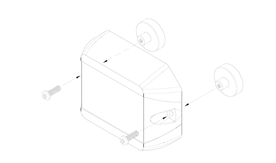
To ensure secure mounting of the magnets, it is important to use only the designated screw points and to ensure that the screws are tightened to a maximum torque of 3 Nm. Depending on the magnet type, M3 stainless steel cylinder head screws are generally suitable for securing the magnets. The magnets themselves must be firmly attached to the housing to prevent slipping or loosening due to vibrations or impacts.
After mounting the magnets, the sensor can be placed on a suitable ferromagnetic surface. Ensure that the contact surface is flat, clean, and sufficiently load-bearing. Unevenness, rust, paint, or dirt can significantly reduce the holding force of the magnets.
Magnetic mounting is particularly suitable for temporary applications, test installations, or locations where tool-free replacement is required. However, it should be noted that mechanical stress or vibrations can reduce the holding force. In safety-critical applications or for permanent installation, it is recommended to additionally secure the sensor or use a fixed screw connection.
Additionally, depending on their material composition, magnets can age more quickly or become porous when exposed to direct sunlight, heat, and weather conditions. Over time, this can lead to a loss of holding force or the sensor slipping out of place. For permanent outdoor applications, therefore, only weather-resistant, encapsulated magnetic mounts should be used, and the sensor should be checked regularly to ensure it is securely fastened.
The general alignment guidelines also apply to magnetic mounting, especially for TH versions with a sensitive membrane: The sensor should always be mounted at an angle of at least 45°, with the membrane facing downward, to prevent water accumulation or particle ingress.
10.8 Wall mounting with adhesive strips
As an alternative to screw mounting or magnetic mounting, the Juno sensor can also be secured using high-quality 3M adhesive strips. The adhesive strips are pre-cut and specially adapted to the shape of the Juno housing to enable quick, clean, and permanent installation, especially on smooth, solid surfaces.
Requirements and Preparation
- The mounting surface must be flat, load-bearing, clean, dry, and free of grease.
- Before application, clean the surface with isopropyl alcohol or a suitable plastic cleaner.
- The adhesive strip should not be used on porous, textured, or very uneven surfaces.
Installation Instructions
- Peel off the protective film from one side of the adhesive strip and apply the strip flat to the back of the sensor. Make sure the strip is aligned precisely and that no air bubbles form.
- Then peel off the second protective film and press the sensor onto the prepared surface with even pressure for about 10-15 seconds.
- The sensor should be left undisturbed for at least 24 hours to achieve full adhesive strength.
Important Notes
- The adhesive bond is designed for long-term use indoors or in protected outdoor areas.
- In environments with high UV exposure, moisture, extreme heat above 80 °C, or constant vibration, adhesive performance may be impaired.
- Correcting the position after application is only possible to a very limited extent.
- For TH versions, the recommended mounting position of at least 45° tilt with the membrane facing down must also be observed.
- The adhesive strips are not reusable. A new adhesive strip must be used when relocating the sensor.
11. Commissioning and Use
Please note that using knives or other sharp objects may damage the housing or electronics.
11.1 Commissioning the sensor with a magnet
There is a magnetic field switch on the sensor for easy activation. The following diagram shows the location of the magnetic field switch.
| Part number | Magnetic field switch |
|---|---|
| S-JUNO(-iX)-MIOTY-TH |
|
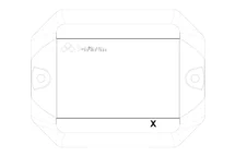
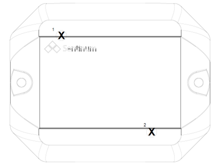
To activate the sensor, hold a standard magnet against the spot marked with an X. We recommend a neodymium magnet with a minimum surface area of 1 cm². The magnet must remain in place for at least 2 seconds until the device activates. This is confirmed by a beep.

Please note that for operation, Hall switch 1 can always be used to detect a flap opening, and magnetic switch 2 can always be used for activation.
11.2 Setting up the sensor via NFC
This activation applies only to the following part numbers:
- S-JUNO(-iX)-MIOTY-TH
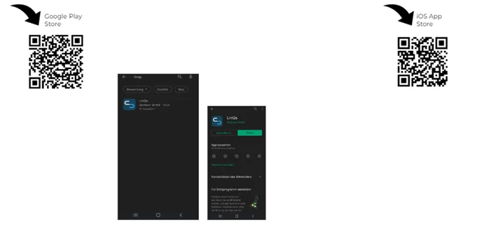
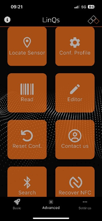
Activation is performed via an NFC app. A smartphone is required for this. The app can be downloaded from the respective app stores. Simply search for Sentinum LinQs and download the LinQs app.
First, locate the tag on the sensor and then the reader on your device. The location of the NFC tag is indicated by the orange arrow.
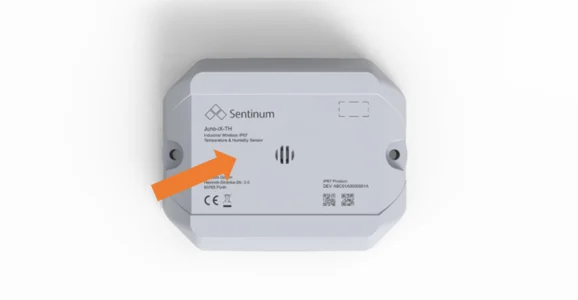
The tag location is also marked on the top surface and labeled Tap here. You can also see the NFC tag location in the technical drawing.
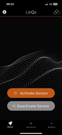
Open the app and activate the sensor. To start the sensor in the basic settings, click the Activate Sensor button in the app start menu. Now place your device on the sensor NFC tag.
When the sensor is activated, Sensor updated! will be displayed. You can then proceed to activate the other sensors.
Depending on the device manufacturer, the NFC readers are located in different places. Their location can be determined by trial and error. Experience shows that they are either further up for iOS devices, or more toward the center for Android.
Activate Sensor
Use the Activate Sensor button to activate the sensor.
Read and set parameters via NFC
Use the Read button to read the parameters.
Set values via NFC
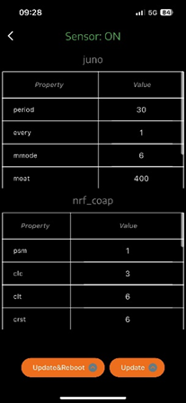
Tap the desired table entry and change the values. Confirm with Update & Reboot or Update at the bottom. Update & Reboot forces a reboot; Update is applied during the next measurement or transmission.
11.3 Audible signal and feedback
- When the device is turned on, an acoustic signal consisting of several rising tones sounds. This tone sequence indicates that the sensor has been successfully activated.
- When the device is turned off, several descending tones are played, acoustically confirming that the device is shutting down.
12. Sensor Functions
The following explains specific sensor functions for the Juno.
12.1 Hysteresis
Hysteresis refers to a behavior in which a system response depends not only on its current state but also on its history. This means that the system remembers where it came from and therefore reacts differently to the same stimulus depending on whether the stimulus is currently increasing or decreasing.
Hysteresis = delay or difference in behavior when a signal or stimulus is rising or falling.
For the Juno, two hysteresis thresholds are specified: one for temperature and one for relative humidity. The values are applied to both the delta and absolute thresholds.
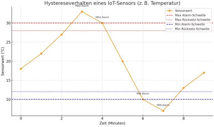
Description:
- Orange line: Sensor values over time.
- Red lines: Dashed line for the maximum alarm threshold; dotted line for the reset point when temperature drops.
- Blue lines: Dashed line for the minimum alarm threshold; dotted line for the reset point when temperature rises.
Example sequence:
- The sensor triggers a MAX Alarm as soon as the value is greater than or equal to 30 °C.
- The alarm remains active until the value drops below 28 °C, and only then is it reset.
- Conversely, the same applies to the lower range with the MIN Alarm at less than or equal to 10 °C.
This behavior prevents alarms from constantly being triggered or deactivated due to minimal fluctuations, a typical feature of hysteresis.
12.2 Inclination and Tilt Detection
Two operating modes are available for Juno sensors with integrated tilt detection:
- Ultra-Low-Power Tilt Detection
This mode is characterized by particularly low power consumption of just 1 µA. It reliably detects an inclination or flap opening starting at approximately 50 degrees. Ideal for applications where coarse inclination detection is sufficient and energy efficiency is a priority. - Advanced Tilt Detection
Additionally, an advanced mode is available that enables degree-accurate detection of tilts or flap openings. Power consumption in this mode depends on the selected sampling frequency but is higher than that of the ultra-low-power variant. This mode is suitable for applications with higher accuracy requirements.
The tilt and flap detection functions and tracking in motion are mutually exclusive.
This means that a sensor with Tracking in Motion enabled cannot perform real-time tilt or flap position detection.
However, the current tilt angle is still transmitted regularly, allowing for a subsequent evaluation of the position.
13. Maintenance and Cleaning
To ensure the sensor functions reliably and has a long service life, it should be maintained regularly. Please observe the following instructions:
- Clean the housing, especially the sensor ventilation slots, with a dry or slightly damp microfiber cloth. Make sure no moisture enters the device.
- Clean the sensor regularly, especially in dusty or pollen-rich environments, to ensure its long-term functionality.
- Do not use cleaning agents containing alcohol or solvents, as these can damage the sensor surface.
- Do not use compressed air or other aggressive cleaning methods, as these can damage sensitive sensor components.
- Hard deposits can impair measurement accuracy. If necessary, clean promptly with a soft, damp cloth and mild detergent.
- Make sure that no leaves, water, or snow are lying on or adhering to the sensor.
14. Battery Replacement
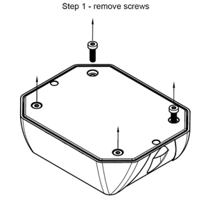
1.
Loosen the 4 screws on the back of the sensor marked with orange arrows. You will need a Torx T10 screwdriver for this, and make sure the seal is not damaged.
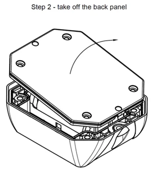
2.
Remove the back cover of the sensor housing. Check that the gasket is seated properly and be careful not to damage it when opening.
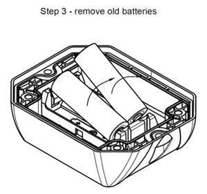
3.
Remove the old batteries from the battery holder.
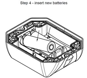
4.
Insert 2 new battery cells. If cells other than those recommended are used, performance and product safety may be compromised, and the operating times and performance specified in the data sheets may not be achieved. After insertion, the sensor should start up with a short beep. As soon as you hear this signal, replace the back cover.
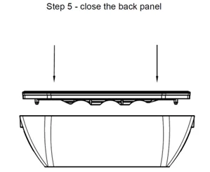
5.
Place the back cover back onto the top of the housing. Make sure the gasket is properly seated and that the housing closes securely.
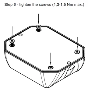
6.
Screw the housing together. Tighten the screws in a crisscross pattern to ensure even and tension-free fastening. Make sure that the original position of the gasket has not been altered. Then reinstall the sensor at its intended location. Dispose of the old batteries in an environmentally responsible manner.
| Part Number | Approved Batteries |
|---|---|
| S-JUNO(-iX)-MIOTY-TH | Energizer Ultimate Lithium AA Varta ULTRA Lithium AA Varta Longlife Power AA SAFT LS14500 (Standard) |
15. Flap opening detection and tilt detection
The lid opening detection can be performed either via the magnetic switch or the accelerometer. The tilt detection feature is performed via the accelerometer.
15.1 Flap opening detection via the magnetic switch
Please note for operation that Hall switch 1 can always be used for detecting a flap opening, and magnetic switch 2 always triggers activation or BLE advertising.
- The magnetic field switch is active. Either one or both sensors can be used.
- Large neodymium magnets are recommended. These should be placed as close as possible to the sensor. A maximum distance of 1 cm between the magnet and the housing is recommended.
- For comparison: With a neodymium disc magnet with d = 20 mm and h = 5 mm, reliable readings are achieved at distances under 1 cm.
- The magnetic field switches can be operated in three different modes: the container is closed when the magnet is applied; the container is open when the magnet is applied; the sensor counts an opening when the magnet passes through twice.
15.2 Flap opening detection using an accelerometer and tilt detection
The Juno sensor is equipped with an integrated 3-axis accelerometer for the reliable detection of changes in motion and position. One of the key functions of this sensor is the detection of the opening of flaps, lids, or enclosures, as typically found in industrial applications.
- Position detection in the idle state:
When the flap is closed, the sensor is in a defined, stable position. The LIS2DTW12 continuously measures acceleration along the X, Y, and Z axes. The static acceleration caused mainly by Earth gravity allows the absolute position of the flap to be clearly determined. - Change in tilt or movement:
If the flap is opened or moved, the sensor orientation in space changes. The sensor detects this change through a significant deviation in the measured acceleration values on at least one axis. This change is interpreted as a trigger event. - Threshold-based detection:
In the Juno firmware setup, an inclination angle or motion threshold can be defined, for example a change of 15 degrees. The sensor can continue to operate very energy-efficiently by setting the angle measurement frequency correspondingly high, for example 5 minutes. As soon as the measured values exceed this threshold, a flap opening event is registered. - Optional: Interrupt-controlled operation:
The sensor supports low-power modes with interrupt triggering. This means that the sensor remains in power-saving mode and only triggers an interrupt to the microcontroller when motion is detected. The disadvantage is that the angle cannot be adjusted and is fixed at 65°. - Event processing and data transmission:
After an opening is detected, the event is logged in the internal memory.
Advantage of this method
- No mechanical components required compared to reed or magnetic switches.
- Insensitive to magnetic field interference.
- Easy retrofitting or customization via software.
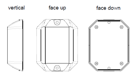
15.3 Orientations
16. Marking and certification