![Logo_quer_farbig.png]](https://docs.sentinum.de/hs-fs/hubfs/Logo_quer_farbig.png?height=40&name=Logo_quer_farbig.png)
1. General Warnings and Safety Instructions
Please note:
- Follow the safety and installation instructions in the operating manual and in the installation guide.
- Ensure that the installation environment meets the specified operating conditions (e.g., temperature limits and environmental conditions).
- The device may only be used for the applications and uses described in the technical areas of application described in the technical specifications.
- Modifications or additions to the device may compromise safety and functionality. In this case, the warranty is void.
- The sensor must not be mounted on ceilings or floors.
- Operation is permitted only up to a maximum altitude of 2,000 m above sea level and in rooms with a maximum height of 2 m.
- A minimum distance of 20 cm must be maintained between the device and people.
- The device may not function properly.
- The device may be permanently damaged.
- There may be a risk of injury.
Please also note:
- Improper mechanical stress, such as from dropping the device, can cause damage to the device.
- The use of unauthorized battery cells can negatively affect performance and product safety .
- The device may only be installed and put into operation if it has been removed from the original packaging undamaged. Immediately after unpacking, a visual inspection for any potential shipping damage.
2. Intended Use and Product Versions
These operating instructions apply to the entire product series Juno.
Within the product series, various product versions are available, which differ in terms of their localization methods, sensor technology, and range of functions.
The specific properties, features, and functions of the respective product variants are described in detail in the following chapters of this operating manual .
| Part Number | Wireless Standard | Functions |
|---|---|---|
| S-JUNO(-iX)-LOEU | LoRaWAN ® | Tilt detection, activity detection, door-opening and motion detection |
| S-JUNO(-iX)-MIOTY | mioty® | Tilt detection, activity detection, door-opening and motion detection |
| S-JUNO(-iX)-LOEU-TH | LoRaWAN® | Temperature, relative humidity, Tilt detection, activity detection, opening and motion detection |
| S-JUNO(-iX)-MIOTY-TH | mioty® | Temperature, relative humidity, tilt detection, activity detection, opening and motion detection |
| S-JUNO-NB-TH | NB-IoT | Temperature, relative humidity, tilt detection, activity detection, door-opening and motion detection |
| S-JUNO(-iX)-LOEU-TRACK | LoRaWAN® | Tilt detection, activity detection, door-opening and motion detection |
| S-JUNO(-iX)-LOEU-TH-TRACK | LoRaWAN® | Temperature, relative humidity, tilt detection, activity detection, door opening and motion detection |
| S-JUNO(-iX)-NBM1-TRACK-2 | NB-IoT, CAT -M1 | Tilt detection, activity detection, door-opening and motion detection |
| S-JUNO(-iX)-NBM1-TRACK-3 | NB-IoT, CAT-M1 | Tilt detection, activity detection, door-opening and motion detection |
| S-JUNO(-iX)-NBM1-TH-TRACK-2 | NB-IoT, CAT-M1 | Temperature, relative humidity, Tilt detection, activity detection, door-opening and motion detection |
| S-JUNO(-iX)-NBM1-TH-TRACK-3 | NB-IoT, CAT-M1 | Temperature, relative humidity, tilt detection, activity detection, door-opening and motion detection |
| S-JUNO(-iX)-MIOTY-TRACK | mioty® | Tilt detection, activity detection, door-opening and motion detection |
| S-JUNO(-iX)-MIOTY-TH-TRACK | mioty® | Temperature, relative humidity, tilt detection, activity detection, opening and motion detection |
Product Codes and Localization Methods
| Part Number | Wireless Standard | Wi-Fi SSID Scan | GNSS Scan | GNSS | Cell Locate | LPWAN Tracking |
|---|---|---|---|---|---|---|
| S-JUNO(-iX)-LOEU | LoRaWAN® | ✖ | ✖ | ✖ | ✖ | ✔ |
| S-JUNO(-iX)-MIOTY | mioty® | ✖ | ✖ | ✖ | ✖ | ✔ |
| S-JUNO(-iX)-LOEU-TH | LoRaWAN® | ✖ | ✖ | ✖ | ✖ | ✔ |
| S-JUNO(-iX)-MIOTY-TH | mioty® | ✖ | ✖ | ✖ | ✖ | ✔ |
| S-JUNO-NB-TH | NB-IoT | ✖ | ✖ | ✖ | ✔ | ✖ |
| S-JUNO(-iX)-LOEU-TRACK | LoRaWAN® | ✔ | ✔ | ✖ | ✖ | ✔ |
| S-JUNO(-iX)-LOEU-TH-TRACK | LoRaWAN® | ✔ | ✔ | ✖ | ✖ | ✔ |
| S-JUNO(-iX)-NBM1-TRACK-2 | NB-IoT, CAT-M1 | ✔ | ✖ | ✔ | ✔ | ✖ |
| S-JUNO(-iX)-NBM1-TRACK-3 | NB-IoT, CAT-M1 | ✔ | ✖ | ✔ | ✔ | ✖ |
| S-JUNO(-iX)-NBM1-TH-TRACK-2 | NB-IoT, CAT-M1 | ✔ | ✖ | ✔ | ✔ | ✖ |
| S-JUNO(-iX)-NBM1-TH-TRACK-3 | NB-IoT, CAT-M1 | ✔ | ✖ | ✔ | ✔ | ✖ |
| S-JUNO(-iX)-MIOTY-TRACK | mioty® | ✔ | ✖ | ✔ | ✖ | ✔ |
| S-JUNO(-iX)-MIOTY-TH-TRACK | mioty® | ✔ | ✖ | ✔ | ✖ | ✔ |
3. Intended Use
The Juno sensor is a battery-powered, wireless IoT device designed to collect environmental and motion data. It was developed for industrial and commercial applications, particularly for condition monitoring and object localization in indoor and outdoor environments.
Depending on the model, , the sensor features various sensor modules—for example, for temperature, motion, or tilt measurements—as well as different localization methods such as GNSS, Wi-Fi SSID scanning, or LoRaWAN®-based positioning.
The sensor may only be used in accordance with this documentation and within the specified technical specifications . Any use deviating from these specifications is considered improper. In such cases, Sentinum GmbH assumes no liability for any resulting damage.
4. Differences Between the iX Versions
The iX models feature advanced industrial certifications, additional accessories, and more precise configuration of measurement and transmission intervals.
While the standard versions support a minimum interval of 5 minutes, the iX variants allow intervals starting at 1 minute.
In addition, the iX models differ from the standard versions in terms of housing color.
| Version | Housing Color |
|---|---|
| Standard version | Black |
| iX industrial version | Silver-gray |
5. Technical Drawing
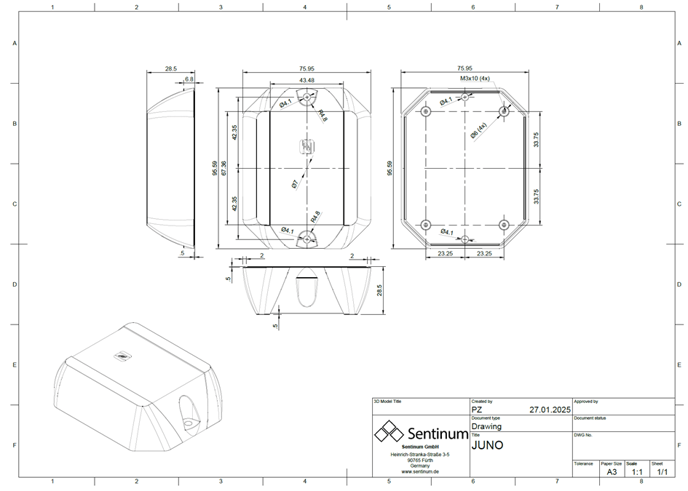
5.1 Technical Drawing Juno
- Juno (without TH)
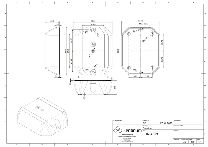
- TechnicalH (with TH opening)
5.2 Scope of Delivery
| Product Version | Scope of Delivery |
|---|---|
| Standard Version |
|
| iX Industrial Version |
|
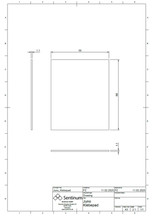
5.3 Adhesive Pad Technical Drawing
Approved batteries and types
6. Approved battery types
| Part Number | Approved Batteries |
|---|---|
|
S-JUNO(-iX)-LOEU S-JUNO(-iX)-MIOTY S-JUNO(-iX)-LOEU-TH S-JUNO(-iX)-MIOTY-TH S-JUNO(-iX)-LOEU-TRACK S-JUNO(-iX)-MIOTY-TRACK S-JUNO(-iX)-LOEU-TH-TRACK S-JUNO(-iX)-MIOTY-TH-TRACK |
|
|
S-JUNO(-iX)-NBM1-TRACK-2 S-JUNO(-iX)-NBM1-TRACK-3 S-JUNO(-iX) -NBM1-TH-TRACK-2 S-JUNO(-iX)-NBM1-TH-TRACK-3 S-JUNO-NB-TH |
|
7. How the Wi-Fi SSID Scan Works
- Passive scan: Receiving beacon frames containing SSID, BSSID, and RSSI values from existing Wi-Fi access points.
- RSSI measurement: Evaluation of signal strength to estimate the distance to individual access points.
- Trilateration: Use of RSSI values in conjunction with known positions of the access points to determine position.
- Refinement and display: Taking environmental conditions and motion information into account, followed by an update of the position display.
Advantages and Areas of Application
- High accuracy indoors where GNSS/GPS is unavailable.
- Cost-effective use of existing Wi-Fi infrastructure.
- Low power consumption, as no constant satellite connection is required.
Typical use cases:
- Indoor navigation, for example in shopping malls or airports.
- Asset and fleet tracking in warehouses, logistics centers, or on company premises.
- Location tracking of battery-powered IoT devices.
Factors affecting accuracy
- Signal variability: RSSI-based distance measurement is not linear. Walls, furniture, and radio interference can affect accuracy .
- Density and placement of access points: Reliable trilateration requires at least three strategically placed access points.
- Algorithm quality: Calibrated or machine learning-based methods can reduce interference and measurement noise.
- Open areas: Approx. 1 to 5 m accuracy
- Complex indoor spaces: Approx. 5 to 20 m accuracy
Advantages of Juno
- Hybrid localization: Combination of Wi-Fi SSID, GNSS, and cellular data.
- Dual-band scan: Active and passive scanning at 2.4 GHz and 5 GHz with detection of up to 20 access points.
- Battery-efficient: Optimized for low power consumption and long battery life.
- Secure: Supports WPA3.
- Actual accuracy: Typically 3 to 20 m, depending on the environment.
How the GNSS scan works
- Satellite positioning: Receiving signals from at least four satellites (GPS, Galileo, GLONASS, or BeiDou).
- Time-of-flight measurement: Distance is calculated using the speed of light and the signal transit time.
- Trilateration: The position is determined from the intersection points of several distance spheres.
- Correction systems: DGPS and SBAS methods compensate for atmospheric, orbital, and time-related errors.
Typical accuracy: Single-GNSS: 2.5 to 10 m, Multi-GNSS: 1 to 3 m (up to 10 to 50 m in urban canyons).
7.1 GNSS and Wi-Fi Data in the LoRa® Cloud
- Data ports: Wi-Fi SSID scan (172), GNSS scan (197)
- Workflow: Device → LoRa® Cloud → Geolocation → Network server
- Integrations: Semtech LoRa Cloud, The Things Stack (TTI), ChirpStack
Requirements
- An active account with The Things Stack (TTI) .
- A registered LoRaWAN® device (e.g., a tracker with GNSS functionality).
- API access to Semtech LoRa Cloud Services via the developer portal: https://lora-developers.semtech.com
- A LoRa Cloud token (API key) from the LoRa Cloud Portal.
Activate Semtech LoRa Cloud
- Open: https://lora-developers.semtech.com
- Create an account or log in.
- Navigate to LoRa Cloud → Modem Services and copy the API key (token) for later use.
Set up integration with The Things Stack
- Log in to the The Things Stack Portal: https://eu1.cloud.thethings.industries/ desired device.
- Navigate to Integrations → Webhooks.
- Select Add Webhook and then Semtech LoRa Cloud as the template.
Configure Webhook
-
Fill out the configuration form
:
- Base URL: Automatically suggested by The Things Stack.
- Token: API key from the Semtech LoRa Cloud.
-
Enable the required services, e.g. nbsp;e.g.,
- Modem Services (GNSS and Wi-Fi scans)
- Geolocation (TDOA- and RSSI-based positioning)
- Depending on the device, additional GNSS or Wi-Fi data may be transmitted.
Customize payload formats (if necessary)
- The end device must use the payload format expected by Semtech , such as the format used by LoRa Basics™ Modem.
Verify data
- As soon as the device transmits location data, it is forwarded by The Things Industries (TTI) to the Semtech LoRa Cloud .
- The cloud's response is then sent back via TTI to the end device or connected application.
Testing and Monitoring
- Use the live data view in TTI to verify the transmitted data.
- Monitor incoming and processed requests in the Semtech LoRa Cloud.
- Verify the returned geodata, such as latitude, longitude, and accuracy information.
This integration works best with devices based on the Semtech LoRa Basics™ Modem-E architecture, such as the LoRa Edge™ LR1110. Custom payload formats can also be used, provided the API calls are compatible.
Port mapping for Wi-Fi SSID scan, GNSS scan, and regular payloads
| Function | LoRaWAN Port | Description |
|---|---|---|
| GNSS scan payload | 197 | Raw data (satellite ID, time information, etc.) for the geolocation backend. |
| Wi-Fi SSID scan payload | 194 | Scanned MAC addresses and RSSI values for position determination. |
| Regular Payload | 1 | Standard sensor data such as temperature, humidity, tilt, battery voltage, and other measurements. |
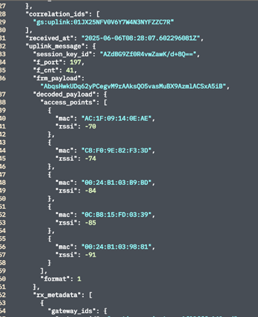
The following providers are recommended for decoding Wi-Fi SSID scan and GNSS scan data:
- Semtech LoRa Cloud (to be discontinued at the end of July 2025)
- AWS
- Tencent
- Traxmate
- Sentinel
For on-premises applications, local databases .
7.2 Tracking in LoRaWAN®
Tracking in LoRaWAN® relies on end devices ("nodes") sending radio signals to multiple gateways.
Positioning does not take place within the device itself, but rather through the network or via a positioning platform such as the Semtech LoRa Cloud®.
Position calculation is based on the received radio signals . Depending on the use case and available infrastructure, different methods or combinations of several methods can be used.
TDOA (Time Difference of Arrival)
- How it works: Each gateway assigns a high-precision timestamp to a node's transmission.
- Multilateration: The time differences between the received signals define hyperbolas. With at least three gateways, a geographic intersection point (latitude and longitude) can be calculated.
- Processing: Position calculation is performed centrally on the network server or in a cloud application.
- Typical accuracy: Approximately 200 to 1,000 m, depending on gateway density, synchronization quality, and environmental conditions.
The gateways must use GPS or PTP (Precision Time Protocol) for precise time synchronization. Even deviations in the microsecond range can lead to significant position errors.
Key factors affecting accuracy:
- Gateway density and gateway layout
- Quality of time synchronization
- Environmental conditions, such as reflections off buildings or other obstacles
- Signal distortions caused by walls, furniture, or machinery can result in time measurement errors.
- Multipath propagation alters the measured arrival times of the signals.
- Positioning at least three gateways with direct line of sight is often difficult in buildings.
- GPS synchronization is often limited or unavailable indoors.
Key factors affecting accuracy:
- Gateway density and spatial arrangement
- Precision of time synchronization
- Environmental conditions, e.g., reflections off buildings
Possible applications:
- Very large indoor areas, such as warehouses, logistics centers, or terminals with high gateway density.
- Use of algorithms to correct for multipath propagation effects.
- Hybrid positioning systems combining LoRaWAN®-TDOA with Bluetooth® , UWB, or Wi-Fi to improve positioning accuracy.
Tracking via the cellular network ("Cell Locate")
Positioning via the cellular network is based on a device's communication with surrounding cellular cells.
Location determination is not performed by the device's GNSS, but rather by analyzing various network parameters
| Method | Typical Accuracy | Note |
|---|---|---|
| Cell ID | 100 m to several km | Very inaccurate; depends on cell size (urban vs. rural areas). |
| Enhanced Cell-ID | 50 to 500 m | Improved accuracy through additional time information, but highly network-dependent. |
| TDOA (Time Difference of Arrival) | 50 to 150 m | Requires multiple synchronized base stations or gateways. |
| AOA (Angle of Arrival) | 100 to 200 m | Less common; special antennas required. |
The accuracy of cellular positioning depends heavily on the positioning method used, network coverage, and the respective environmental conditions. Energy consumption is generally very low compared to other positioning technologies.
eDRX: On the Way to a Query-Enabled Tracker
eDRX (Extended Discontinuous Reception) is a feature available exclusively on mobile devices.
eDRX enables the creation of a tracker that is constantly reachable and at the same time energy-efficient, which can be queried remotely as needed.
How eDRX Works
- Sleep Mode: After a transmission, the device interrupts its regular network queries and switches to a power-saving mode.
- Extended reception intervals: Instead of continuously monitoring the network, the device only listens for incoming messages at set intervals, for example, once per minute or just once per hour.
- Wake-up cycle: At each defined eDRX time, the device briefly activates its receiver, processes any commands or requests, and then returns to sleep mode again.
- Significantly lower energy consumption during idle phases.
- The device remains registered on the cellular network.
- Location and status queries can be performed on demand.
Planning and Design Considerations
- Cycle length: Possible eDRX intervals range from a few seconds to several hours, depending on the cellular network and its configuration.
- Consideration: Shorter wake-up intervals increase the device's device but result in higher energy consumption.
- Optimization: The selected polling interval should always be determined with consideration of the desired battery life and the availability requirements.
8. General Handling Instructions
-
Transport and Storage
- Transport and store the sensor in its original packaging whenever possible to prevent mechanical damage and electrostatic discharge.
- Store the device exclusively within the environmental conditions specified in the technical data sheet.
-
Installation
- Use only the designated mounting points on the housing.
- Ensure a stable and, as far as possible, vibration-free installation to guarantee optimal measurement accuracy .
-
Commissioning
- Insert the battery correctly and check that it is sufficiently charged.
- Activate the sensor using the built-in magnetic switch or the smartphone app (depending on the model).
- For initial setup, use the software or app provided by Sentinum .
-
Operation
- Operate the device exclusively within the specified environmental conditions regarding temperature, humidity, and protection class.
- Avoid strong magnetic fields and metallic shielding, as these can interfere with the wireless connection and sensor functions.
-
Cleaning
- Clean the housing as needed with a slightly damp, lint-free cloth.
- Do not use harsh cleaning agents, solvents, or abrasive cleaners.
- Tracker variants without a TH module and without an opening in the housing have an IP69K protection rating and are suitable for corresponding cleaning procedures.
-
Maintenance
- Juno sensors are largely maintenance-free. Depending on the usage profile, a battery replacement may be necessary after several years.
- Regularly check the device's functionality as well as the connection to the backend system.
-
Disposal
- Dispose of the device at the end of its service life in accordance with applicable regulations for waste electrical and electronic equipment and batteries.
8.1 Special Handling Instructions for TH Versions
The Juno TH versions feature a sensitive membrane that enables air exchange for precise temperature and humidity measurement.
Follow the instructions below to ensure the long-term functionality and accuracy of the sensor system.
- The diaphragm is sensitive to mechanical stress. Never insert pointed or sharp objects into the opening.
- Avoid contamination from dust, metal shavings, or other particles. Blockages can compromise measurement accuracy.
- Never clean or replace the membrane yourself. Contact only the manufacturer or authorized technicians for this purpose.
- Keep cleaning agents away from the membrane. Harsh chemicals can permanently or alter its permeability.
Installation Instructions
- Despite the IP67 protection rating, you should prevent standing moisture from collecting at the membrane opening, as this can distort the measured values.
- For outdoor use, installation at an angle of at least 45° is recommended so that the membrane faces downward.
- Do not install the sensor near the ground or in areas with heavy splashing water to prevent the ingress of dirt, mud, or water.
Additional Notes
- Ensure adequate air circulation: Avoid completely enclosed housings or heavy shielding. Unobstructed airflow is required for precise measurements.
- Avoid UV radiation: Prolonged direct sunlight can damage the housing and diaphragm. Installation in partial shade or under a small protective cover is recommended.
- Avoid condensation: Significant temperature fluctuations can lead to the formation of moisture at the diaphragm opening. Therefore, the opening to face downward.
- Do not paint or coat: Even thin coatings can seal the diaphragm and cause significant measurement errors.
- Avoid aggressive atmospheres: High concentrations of solvent vapors, sulfur compounds, or similar substances can damage the membrane and electronics. Use the device only in approved environments.
9. Assembly and Installation
Warning and Safety Instructions for Installation
If the sensor remains easily accessible after installation, mount the sensor first and then activate it.
If the sensor is no longer accessible after installation, activate the sensor first and mount it only afterward.
Before mounting, ensure that the intended mounting surface is level. Uneven surfaces can cause damage to the housing.
Please note:
- Do not insert any objects or body parts into the openings of the sensor.
- Do not mount the sensor on ceilings or directly on the floor.
- Do not install the sensor at heights exceeding two meters.
- Install the sensor exclusively indoors on a wall in a standard room. The recommended mounting height is 1.50 m to 1.80 m.
- Protect your hands and fingers. Strong magnets can suddenly attract each other and cause injuries. Keep a safe distance and wear protective gloves if necessary.
- Keep electronic devices away. Magnetic fields can interfere with smartphones, credit cards, pacemakers, and other electronic devices.
- Be aware of the risk of breakage. Many magnets are brittle and can shatter if struck.
- People with implanted medical devices should avoid strong magnets or seek medical advice in advance.
- Store magnets separately from other magnets and metal parts to prevent uncontrolled attraction.
- Keep small magnets out of the reach of children to avoid the risk of swallowing.
- Do not heat magnets beyond their permissible operating temperature (typically 80 °C to 200 °C, depending on the magnet type).
Recommended Mounting Methods
| Mounting Type | Description | Recommended Accessories |
|---|---|---|
| Screw connection | Mounting with 2 × M4 or M5 screws | 2 × suitable countersunk screws (wood screws with a diameter of 4–5 mm, if necessary) |
| Magnetic mounting | Installation with 2 × neodymium pot magnets with M4 internal thread | 2 × neodymium magnets for indoor use, total load capacity 16–32 kg |
| Adhesive mounting | Mounting using double-sided adhesive tape or mounting adhesive | High-strength double-sided adhesive tape or approved mounting adhesive |
10. General Installation Instructions
Installation of Juno Tracker Versions (without housing opening)
- Select an installation location within the permissible environmental conditions and temperature ranges as specified the technical specifications.
- The housing must not be covered. Wireless communication (e.g., LoRaWAN® or Bluetooth® Low Energy) must not be impaired by metal housings, metallic objects, or other shielding materials.
- For optimal wireless connectivity, the device should have as unobstructed a view of the sky as possible.
- Securely mount the sensor, preferably using the provided mounting holes, on a low-vibration or stable surface.
- The standard version requires no special orientation and can be mounted horizontally, vertically, or flat, depending on the application.
- Do not install the sensor in the immediate vicinity of strong sources of electromagnetic interference.
1️0.1 Installation Instructions for Juno TH Versions
- The sensor must be mounted at an angle of at least 45° so so that the diaphragm faces downward. This prevents water or dirt from entering the opening.
- Avoid mounting the sensor near the ground or in areas prone to splashing water. Install the sensor at a higher elevation and protected from contamination.
- Ensure adequate air circulation and do not use enclosed housings without ventilation.
- Direct sunlight should be avoided to prevent overheating and measurement errors. A partially shaded installation or a small weather shield is recommended.
- Avoid dusty or chip-laden environments, such as workshops or grinding areas.
- The diaphragm opening must never be glued, sealed, or painted over.
- Cleaning or replacement of the diaphragm may only be performed by authorized technicians in consultation with the manufacturer.
10.2 Installation Instructions for Tracker Versions
- The GNSS sensor should be mounted outside of metal enclosures to ensure optimal satellite reception .
- Avoid mounting the sensor in the immediate vicinity of large metal surfaces or metal structures.
- Ensure the clearest possible view of the sky to maximize GNSS performance.
- Maintain a distance of at least 30 cm from metallic materials in front of and to the sides of the sensor.
- Do not install the sensor near high-voltage power lines or strong electromagnetic fields.
- Avoid enclosed spaces or covers that may block GNSS signals.
- For mobile use, ensure that the sensor is mounted securely and vibration-proof during operation.
10.3 Important Note for Devices with an External Antenna
If you have ordered a device with an external antenna, identifiable by the gold-colored RP-SMA connector, first install the supplied antenna.
- External antenna: The antenna should always be mounted vertically and, if the application allows it , with the tip pointing upward. Maintain a minimum distance of 2 cm from metal surfaces and avoid shielding caused by surrounding metal parts.
- Internal Antenna: Devices with an internal antenna (without a visible external antenna) should be mounted vertically with the long side of the housing to achieve maximum radio performance. The antenna is located in the upper part of the housing on the side with the logo and should also be at least 2 cm away from metal surfaces. If possible, avoid shielding caused by metal parts.
- Please note: Devices with an external antenna must never be operated without the antenna connected. This can cause irreparable damage to the sensor.
Never operate devices with an RP-SMA connector without a connected antenna. Operating the device without an antenna can permanently damage the radio module.
11. Wall Mounting with Screws
The Juno Sensor can be permanently and securely mounted on a wall or another solid surface. Mounting is performed using the mounting holes provided in the housing.
Preparing for Installation
- Determine the installation location: Select a vibration-free and dry installation location that meets the requirements of the respective sensor variant. For TH versions, for example, ensure sufficient air circulation .
- Check the mounting surface: Suitable substrates include concrete, masonry, wood, or engineering plastic panels. For porous or soft materials, appropriate anchors should be used.
-
Prepare tools and fasteners:
- Cordless screwdriver or screwdriver with torque limiter
- Drill bits suitable for the respective wall material
- Suitable anchors (if necessary)
- Appropriate screws according to the installation instructions (see below)
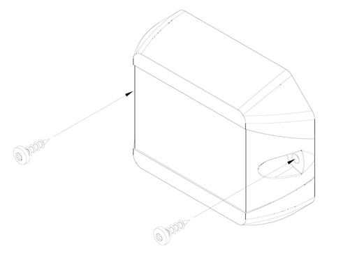
Screw Selection
- The mounting holes in the sensor housing are designed for M4 screws.
-
Depending on the mounting surface, the following
fasteners are recommended:
- M4 cylindrical screws (e.g., DIN 912, stainless steel) for plastic housings or metal frames.
- Spax screws 4 × 30 mm with suitable anchors for concrete, brick or wooden walls.
- The screws must be able to pass freely through the housing without deforming or damaging it.
Installation Instructions
- Maximum tightening torque: 3 Nm. Higher torques can lead to housing deformation or damage.
- Tighten the screws evenly and without applying excessive tension.
- Ensure that the housing rests flat and that no mechanical stresses are created.
- Do not drill any additional holes or make any modifications to the housing.
- Do not install with the opening facing upward if condensation or dirt can enter.
- Wear appropriate protective equipment during installation, such as safety glasses when drilling.
- After installation, check by gently pulling and pushing to ensure the housing is securely fastened .
- Ensure that no cables or electrical wires are located behind the mounting surface and could be damaged.
- For TH versions, observe the recommended angle of inclination of at least 45° and ensure that the diaphragm opening faces downward.
Requirements and Preparation
- The mounting surface must be level, stable, clean, dry, and free of grease.
- Clean the surface before installation with isopropyl alcohol or a suitable plastic cleaner.
- The adhesive tape should not be used on porous, textured or highly uneven surfaces, as this may impair adhesion.
Installation Instructions
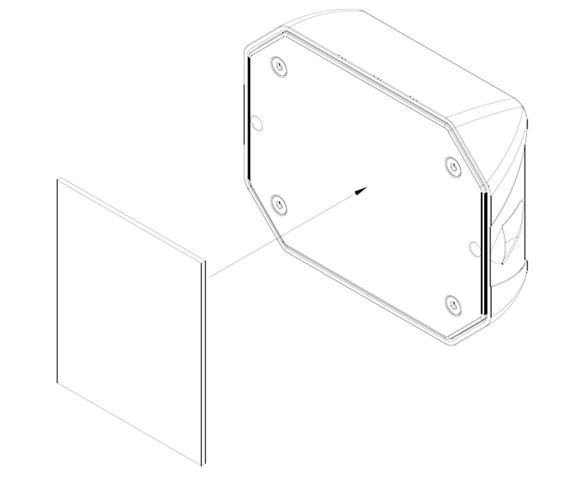
- Remove the protective film from one side of the adhesive strip and apply the strip flat to the back of the sensor. Use the provided markings provided for alignment. Avoid air bubbles and ensure precise positioning.
- Then remove the second protective film and press the sensor evenly onto the prepared mounting surface for about 10 to 15 seconds.
- Then allow the sensor to adhere undisturbed for at least 24 hours so that full adhesive strength can be achieved.
Important Notes
- The adhesive bond is intended for permanent use in indoor areas as well as in protected outdoor areas .
- High UV exposure, moisture, temperatures above 80 °C, or constant vibrations can impair the adhesive strength .
- Position adjustments after bonding are only possible to a limited extent.
- For TH versions, even with adhesive mounting, the recommended installation orientation—with a minimum angle of 45° and the diaphragm opening facing downward.
- The adhesive strips are not reusable. When relocating the sensor, a new adhesive strip must be used.
Maximum adhesive strength is only achieved after a sufficient curing time. Avoid subjecting the sensor to mechanical stress during the first 24 hours.
Commissioning and Use
The housing and electronics may be damaged if knives or other sharp objects are used during installation or activation.
Commissioning the Sensor with a Magnet
The sensor features a built-in magnetic field switch for easy activation of the device.
The following figure shows the location of the magnetic field switch.
| Part Number | Approved Batteries |
|---|---|
|

|
To activate the sensor, hold a standard magnet against the spot marked with "X". We recommend using a neodymium magnet with a minimum surface area of 1 cm².
The magnet must be held in this position for at least 2 seconds to trigger activation.
Successful activation is confirmed by an audible tone.
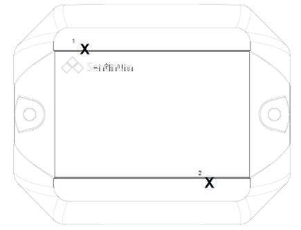
During operation, please note that Hall switch 1 can be used at any time to detect a flap opening, and magnetic switch 2 is always triggered to activate or reset BLE.
12. Commissioning the Sensor via BLE (Quick Start Guide)
This BLE activation applies exclusively to the following part numbers:
- S-JUNO(-iX)-LOEU/MIOTY-TRACK
- S-JUNO(-iX)-LOEU/MIOTY-TH-TRACK
- S-JUNO(-iX)-NBM1-TRACK-2
- S-JUNO(-iX)-NBM1-TRACK-3
- S-JUNO(-iX)-NBM1-TH-TRACK-2
- S-JUNO(-iX)-NBM1-TH-TRACK-3
- Set the sensor to BLE advertising mode so that the Juno can be detected and found by BLE-enabled devices.
To activate advertising mode
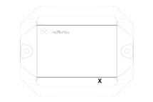
To activate advertising mode, hold a standard magnet to the position marked in the image on the housing.
- Hold the magnet near the housing for at least 2 seconds,
- or place it directly on the marked spot for a moment.
Advertising mode will then start automatically.
13. Sensor Setup via NFC
This activation method applies exclusively to the following part numbers:
- S-JUNO(-iX)-LOEU/MIOTY
- S-JUNO(-iX)-LOEU/ MIOTY-TH
- S-JUNO-NB-TH
Activation is performed using an NFC-enabled smartphone app. This requires a smartphone with NFC enabled.
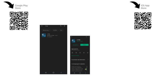
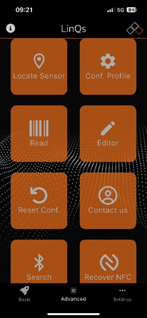
The app can be downloaded from the respective app stores . Search for "Sentinum LinQs" and install the LinQs app on your smartphone.
First, locate the tag on the sensor, and then position the reader on your device. The NFC tag is located where the orange arrow points.
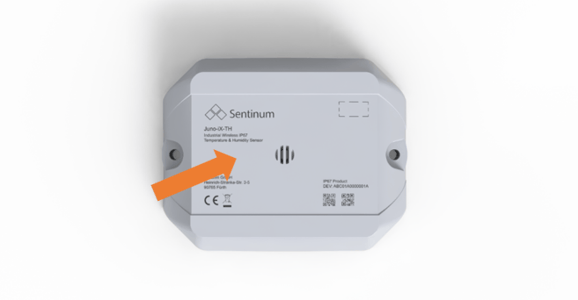
The position of the NFC tag is also marked on the top of the device with the label "Tap here" .
The exact position of the NFC tag can also be found in the technical drawing of the device.
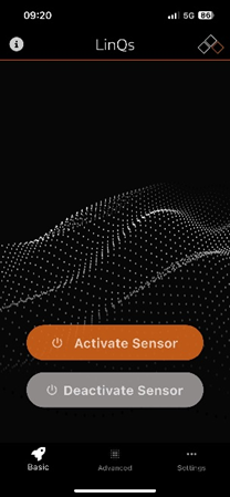
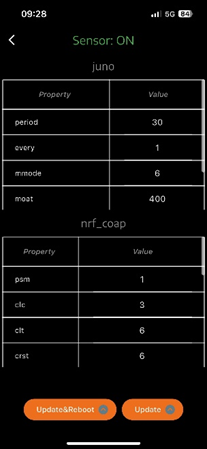
Open the app and activate the sensor.
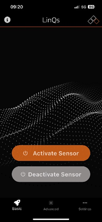
To put the sensor into operation with the default settings , select the function "Activate Sensor" in the app's start menu.
Then place your mobile device on the sensor's NFC tag.
Once activation is successful, the message "Sensor updated!" appears.
You can then activate additional sensors in the same way .
| Step | Description |
|---|---|
 |
Activate Sensor: |
 |
Read and set parameters via NFC: |
 |
Set values via NFC: |
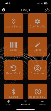
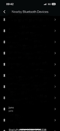
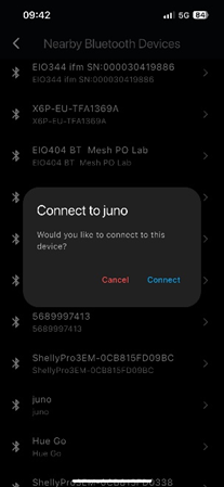
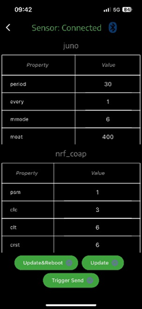
Sensor Setup via BLE
| Cross-section | Description |
|---|---|
 |
Enable BLE advertising mode: |
 |
Search for a BLE device: |
 |
Connect to the sensor via BLE: |
 |
Connect to the sensor via BLE: |
 |
Configure via BLE with the sensor: |
 |
Configure via BLE with the sensor: |
Audible Signal and Feedback
- When the device is turned on, an audible signal sounds consisting of several ascending tones. This tone sequence confirms that the sensor has been successfully activated.
- When the device is turned off, several descending tones are played. This provides an audible indication acoustically signals the successful shutdown of the device.
- When establishing or disconnecting a Bluetooth® connection (BLE), the sensor also emits an audible signal to confirm the respective connection status.
14. Sensor Functions
The following section explains specific functions and settings of the Juno sensor.
Hysteresis
Hysteresis describes a behavior in which a system's response does not depend solely on the current measured value, but is also influenced by the previous history.
The system thus "remembers" its previous state and can react differently to the same measured value, depending on whether the value is currently increasing or decreasing.
Put simply, hysteresis refers to a defined delay or difference in switching behavior between rising and falling measured values.
Two hysteresis thresholds are defined for the Juno sensor:
- Hysteresis for temperature
- Hysteresis for relative humidity
These hysteresis values apply to both delta thresholds and absolute thresholds.
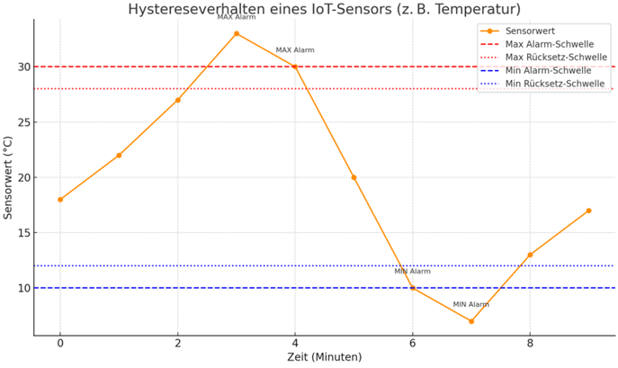
Description:
- Orange line: Sensor values over time.
-
Red lines:
- Dotted ( --): Maximum alarm threshold (e.g., 30 °C).
- Dotted (---): Reset point when temperature drops (e.g., 28 °C).
-
Blue lines:
- Dashed (--): Minimum alarm threshold (e.g., 10 °C).
- Dotted (---): Reset point when the temperature rises (e.g., 12 °C).
Example sequence:
- The sensor triggers a MAX alarm, as soon as the measured value is ≥ 30 °C.
- The alarm remains active until the measured value drops below 28 °C . Only then is the alarm reset.
- Similarly, a MIN alarm is triggered as soon as the measured value is ≤ 10 °C.
This behavior prevents even small fluctuations in the measured value from causing constant triggering and resetting of alarms. This method is referred to as hysteresis.
Tracking and Motion Detection
The device is located independently of the transmission of sensor data such as temperature, tilt angle, or humidity.
This means:
- The interval for position determination can be configured independently of the transmission intervals for the sensor data .
- The sensor readings are recorded and transmitted independently of the tracker's motion status, regardless of whether the device is moving or at rest.
- Position determination can be performed either on a time-based schedule at fixed intervals or on an event-based schedule, for example, when motion is detected or other activity events occur, .
Tilt and Tilt Detection
For Juno sensors with integrated tilt detection, two different operating modes:
-
Ultra-Low-Power Tilt Detection
This operating mode is characterized by particularly low power consumption of just 1 µA. Tilting or the opening of a flap is reliably detected starting at approximately 50°. The mode is particularly suitable for applications where coarse tilt detection is sufficient and maximum battery life is a priority. -
Advanced Tilt Detection
This mode enables significantly more precise detection of tilts and flap openings. Power consumption depends on the selected sampling rate and is higher than that of the ultra-low-power variant. It is suitable for applications with higher accuracy requirements.
The functions tilt or flap detection and motion tracking are mutually exclusive.
This means that a sensor with motion tracking enabled cannot perform real-time tilt or flap detection.
However, the current tilt angle continues to be transmitted regularly and can be evaluated later.
Communication with the Interface
The configuration of sensor communication and join behavior depends on the respective product variant and is described in the corresponding generic documentation for LoRaWAN®, mioty®, or Cellular (NB-IoT and LTE-M).
The complete cross-product documentation can be found at: https://docs.sentinum.de/wichtig-produktübergreifende-dokumentation-für-sensoren
Maintenance and Cleaning
To ensure reliable operation and a long service life of the sensor, we recommend regular cleaning and visual inspection.
- Clean the housing and any ventilation openings with a dry or slightly damp microfiber cloth. Make sure that no moisture enters the device .
- Perform cleaning regularly, especially in dusty, pollen-rich, or industrial environments to ensure the sensor's long-term functionality .
- Do not use alcohol-based cleaning agents, solvents, or other harsh chemicals, as these can damage the surfaces.
- Do not use compressed air or other aggressive cleaning methods, as sensitive sensor components could be damaged.
- Hard deposits such as lime, oil, or grease residues can compromise measurement accuracy. Remove such contaminants promptly using a soft cloth and a mild cleaning agent.
- Make sure there are no leaves, water, ice, or snow on the sensor, as this can affect sensor performance.
15. Battery Replacement
-
Loosen the four screws on the back of the
sensor, marked with orange arrows.
- Use a Torx T1 0 screwdriver.
- Be careful not to damage the gasket when opening the housing.
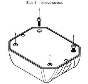
Figure 13. Location of the case screws for battery replacement
After replacing the battery, ensure that the gasket is seated correctly and that the housing is completely sealed again, to maintain the sensor's protection rating .
-
Remove the back cover of the sensor housing.
Check that the gasket is seated correctly, and be careful not to damage it when opening the housing .
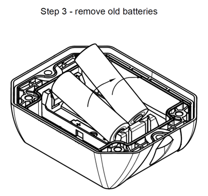
Figure 14. Opening the housing and checking the gasket -
Remove the old batteries from the battery holder.
Figure 15. Removing the battery cells -
Insert two new battery cells.
If uses battery types other than those recommended may compromise performance, product safety, and the specified operating times.
After inserting the batteries, the sensor starts automatically and confirms this with a short beep.
As soon as this beep sounds, replace the back cover of the housing.
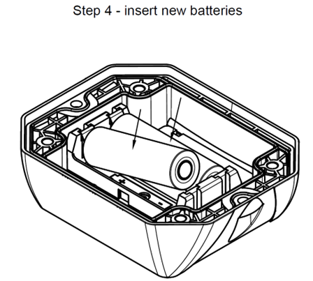
Figure 16. Inserting the new batteries -
Replace the back cover on the top part of the
case.
Make sure the gasket is seated correctly and that the case can be closed completely and without tension .
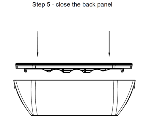
Figure 17. Installing the Housing Back Panel -
Screw the housing back together.
Tighten the screws in a crisscross pattern to ensure an even and tension-free seal of the enclosure.
Finally, check that the position of the gasket has not shifted.
Then reinstall the sensor at its intended location and dispose of the old batteries in accordance with applicable environmental regulations.
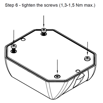
Figure 18. Closing and Securing the Housing
After replacing the battery, check that the sensor is functioning correctly and that the housing gasket is properly seated to ensure the device's protection rating.
Flap detection and tilt detection
Flap detection can be performed either via the magnetic switch or via the accelerometer.
Tilt detection (tilt function) is performed via the accelerometer.
Flap detection via the magnetic switch
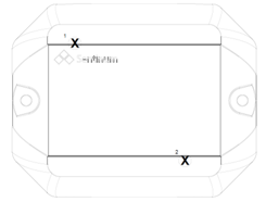
For operation
The following applies during operation: Hall switch 1 can be used at any time to detect a flap opening, and magnetic switch 2 is always used to activate or trigger the BLE.
- The magnetic field switch is active. Either one or both sensors can be used.
- Large neodymium magnets are recommended. These should be placed as close as possible to the sensor. Due to the variable size of the magnets, no standard distance can be recommended. A maximum distance of 1 cm between the magnet and the housing is recommended.
- For comparison: With a neodymium disc magnet (d = 20 mm, h = 5 mm), reliable results are achieved at distances under 1 cm.
- The magnetic field switches can be operated in three different modes:
- The container is closed when the magnet is in contact.
- The container is open when the magnet is in contact.
- The sensor detects an opening when the magnet is pulled through twice.
Flap-Opening Detection with Accelerometer and Tilt Detection
The Juno sensor is equipped with an integrated 3-axis accelerometer that reliably detects changes in motion and position. A key function is the detection of flap, lid, or housing openings—typical for industrial applications.
- Position detection in the idle state:
- When the flap is closed, the sensor is in a defined, stable position.
- The LIS2DTW12 continuously measures acceleration along the X, Y, and Z axes.
- The absolute flap position can be uniquely determined via what is known as static acceleration (primarily caused by Earth's gravity).
- Change in tilt or movement:
- If the flap is opened or moved, the sensor's orientation in space changes.
- The sensor detects this change through a significant deviation in the measured acceleration values on at least one axis.
- This change is interpreted as a trigger event.
- Threshold-based detection:
- An inclination angle or a motion threshold can be defined in the Juno firmware (e.g., a change of 15°, not in ultra-low-power mode). The sensor can, of course, be operated very energy-efficiently if the angle measurement frequency is set accordingly high, e.g., 5 minutes. The measurement is then negligible in relation to total power consumption.
- As soon as the measured values exceed this threshold, a flap opening event is registered.
- Optional: Interrupt-controlled operation:
- The sensor supports low-power modes triggered by interrupts.
- This means that the sensor remains in power-saving mode and only triggers an interrupt to the microcontroller when motion is detected—ideal for extending battery life.
- Disadvantage: The angle cannot be adjusted and is fixed at 65°.
- Event processing and data transmission:
- After an opening is detected, the event is logged in the internal memory.
- Depending configuration, a data packet can be sent immediately via LoRaWAN, BLE, or another protocol.
Advantages of this method
- No mechanical components required (compared to reed or magnetic switches)
- Insensitive to magnetic interference
- Easy retrofitting or customization via software
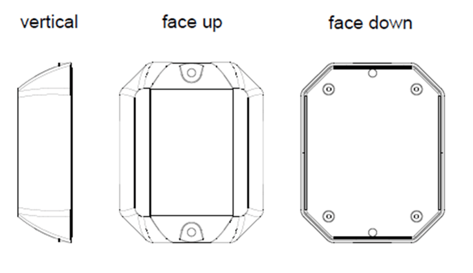
Orientations
16. LoRaWAN®-Specific Functions
LoRaWAN® Join Behavior
Before telemetry data can be transmitted via LoRaWAN®, the device must first establish a connection to the network .
To do this, the device sends so-called Join requests until a valid Join-Accept is received from the network.
To achieve a balanced compromise between power consumption and connection establishment, the time intervals between Join requests are gradually increased.
In addition, the data rate is adjusted. Initially, the device attempts to establish a connection using a high data rate or a small spreading factor (SF). If a connection cannot be established, lower data rates or larger spreading factors are then used.
The join behavior follows the guidelines and recommendations of the LoRa Alliance® specification.
Sentinum sensors implement these requirements using so-called join bursts, whose time intervals increase with each subsequent connection attempt.
A join burst consists of a maximum of six join requests with decreasing data rates (DR5 to DR0) or increasing spreading factors (SF7 to SF12).
The time intervals between individual Join Requests are increased quadratically to comply with the duty cycle requirements of the LoRa Alliance.
The following duty cycle limits apply to join requests:
| Time Period | Duty Cycle |
|---|---|
| < 1 hour | 1 % |
| < 11 hours | 0.1 % |
As a result, the same transmission time budget is available in the first phase (< 1 hour) as in the second phase (< 11 hours), even though only one-tenth of the time span can be utilized.
To make optimal use of this budget, the intervals between the individual join bursts are initially short and then gradually increase.
Specifically:
- two join bursts are performed in Phase 1,
- two additional join bursts are performed in Phase 2,
- Starting in Phase 3, one join burst is performed per day.
The duration of a join burst increases from about 10 minutes in Phase 1 to about 100 minutes in Phase 2 and up to about 16 hours in Phase 3.