![Logo_quer_farbig.png]](https://docs.sentinum.de/hs-fs/hubfs/Logo_quer_farbig.png?height=40&name=Logo_quer_farbig.png)
- Symbols and Explanations
- Safety Instructions
- Technical Drawing
- General Operating Principle of the Apollon-Q PP
- Additional Use Cases
- Recommended Accessories
- Mounting Accessories
- Installation and Preparation
- General Installation Instructions
- Rear Wall Mounting with Screws
- Front Wall Mounting with Screws
- Rear Wall Mounting with Magnets
- Front Wall Mounting with Magnets
-
Scope of Delivery for Installation with Blind Rivets or Rivet Nuts
- 14.1 Rivet Nuts
- General Information on Front Wall Mounting with Rivet Nuts
- Front Wall Mounting with Rivet Nuts
- Rear Wall Mounting with Rivet Nuts
- General Information on Blind Rivet Installation
- Rear Wall Mounting with Blind Rivets
- Front Wall Mounting with Blind Rivets
- Hall Switch Mounting Instructions
- NFC Commissioning and NFC Tag Location
- Battery Replacement
Symbols and Explanations
Important warnings and information about potential hazards, malfunctions, or damage.
Important information for proper operation, configuration, and installation of the device.
Important information regarding preventive safety measures.
1. Safety Instructions
- Follow the safety instructions and installation instructions in the manual and in the installation documentation.
- Ensure that the installation environment complies with the prescribed guidelines for the respective application. Adhere to temperature and other limit values at all times.
- The device may only be operated within the ranges specified in the technical data.
- The device may only be used for the intended purpose described.
- Modifications or additions to the device may safety, functionality, and approval can no longer be guaranteed.
- Improper installation may cause the device to malfunction .
- Improper installation can cause permanent damage to the device.
- Improper assembly may pose a risk of injury.
- Improper handling, such as subjecting the device to heavy mechanical stress or dropping it, can cause damage and malfunctions.
3. Technical Drawing
.png?width=688&height=407&name=Untitled%20%20(37).png)
The front side is the side where the logo and the central opening for the sensor are located. The back side is the side where the labeling (e.g., company address) is affixed.
4. General Operation of the Apollon-Q PP
The Apollon-Q PP is a sensor for detecting the presence of objects and goods. The sensor can be used, for example, to detect packages or pallets on shelves.
In this example, a shelf with four stacked items is used.
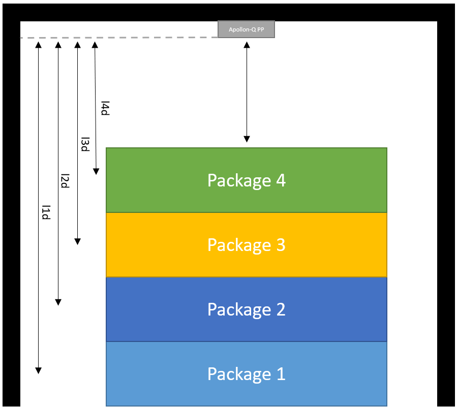
Depending on the set measurement frequency, the sensor detects the presence of the packages using optical time-of-flight distance measurement. The measurement frequency can be set using the "Measurement Period" parameter (mper). The default value is 5000 ms.
For reliable detection of the packages, the distances should always be set to approximately half the height of the packages, as shown in the figure. l4d should therefore be the distance from the sensor to Package 4 plus half the height of Package 4. If the measured distance from the sensor is less than the set distance l4d , the sensor has detected an object in the area of Level 4.
If Package 4 is on the shelf, the sensor returns the following values in the payload:
...object_present: true,object_level: 4,object_distance: [Distance to the object],
.. .
If Package 4 is removed from the shelf, a beep sounds and the sensor sends a message due to the change in state. The distance is then measured and compared to the set levels. In this case, the measured distance is less than the set distance l3d and the sensor has detected an object at Level 3. Here, the sensor returns the following data in the payload:
...object_present: true,object_level: 3,object_distance: [Distance to the object],
...
This behavior can be applied analogously to the removal of packages 1 through 3.
If a distance outside the defined limits is measured, the sensor changes its state from Level 1 to "no object detected" and adjusts the payload as follows:
.. .object_present: false,object_level: 0,object_distance: [Distance to object],
...
This state occurs when a distance greater than l1d is detected. Thus, if there is no package on the shelf, this is acknowledged with object_present: false .& nbsp;
The sensor transmits the data no later than the defined measurement interval whenever a state change occurs. Additionally, a handshake can be configured.
In general, up to 4 different levels can be defined in the sensor. The values can be configured via NFC or downlinks:
| Name | Description | .json key |
|---|---|---|
| Distance Level 1 | Distance to trigger a Level 1 state change | l1d |
| Distance Level 2 | Distance to trigger a Level 2 state change | l2d |
| Distance Level 3 | Distance to trigger a Level 3 state change | l3d |
| Distance Level 4 | Distance to trigger a Level 4 state change | l4d |
l1d always represents the greatest distance here—that is, the distance to the object farthest from the sensor.
l4d always represents the smallest distance here—that is, the distance to the object closest to the sensor.
Not all distances need to be defined. If you only need to distinguish between two objects, you can use the parameter lvls to set the number of active levels/ levels. The levels are then activated in ascending order. If the parameter lvls = 2, then the distance for Level 1 (l1d) and the distance for Level 2 (l2d) can be set.
The dyn parameter can be used to specify whether the sensor can distinguish between current levels or not. If dyn=1, the sensor returns the current level, distance, and object_present; if dyn=0, the sensor returns only object_present:true or object_present:false.
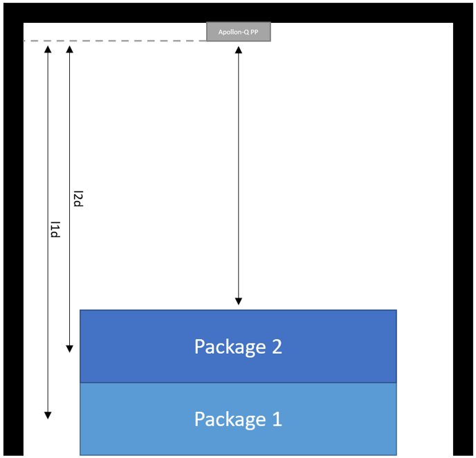
Considering this specific case, the number of levels can be set to lvls=2 to meet the application requirements. In this case, the maximum capacity of the shelf is two packages.
5. Additional Use Cases
Depending on the sensor's configuration, various use cases can be implemented. The following scenarios were implemented as examples:
- Detection and presence of vehicles (industrial trucks, cars, trucks, etc.)
- Detection of open doors or hatches
- Detection of packages in shipping boxes
6. Recommended Accessories
| Type | Recommended Accessories | Sentinum Part Number | Manufacturer |
|---|---|---|---|
| Screws (Wall) |
DIN912 cylinder head screws or wood screws with anchors
appropriate for the wall material.
Acceptable sizes:
|
- | - |
| Magnet | Neodymium magnet with M4 internal thread | - | - |
| Adhesive | Mounting adhesive | - | - |
| Adhesive stickers | Double-sided tape | - | - |
7. Mounting Accessories
| Part Number | Recommended Accessories |
|---|---|
| Z-APOQ-MAG-NEO | APOQ Neodymium Magnet Set |
| Z-APOQ-MAG-FER | APOQ Ferrite Magnet Set |
| Z-APOQ-RWM-BN | Rear Panel Mounting Kit with Blind Rivets |
| Z-APOQ-RWM-NM | Rear Panel Mounting Kit with M4 Rivet Nuts |
| Z-APOQ-VWM-BN | Front Panel Mounting Kit with Blind Rivets |
| Z-APOQ-VWM-NM | Front panel mounting kit with M4 rivet nuts |
| Z-APOQ-AP | PA Spacer Plate |
| Z-APOQ ADHESIVE | Assembly Adhesives |
| Z-APOQ-SCREWS | DIN 912 machine screws with M4 nuts |
| Z-APOQ-SPX | Wood screws |
| Z-APOQ-DKLB | Double-sided adhesive tape |
8. Installation and Preparation
If the sensor is easily accessible after installation, install the sensor first and do not activate it after mounting it.
If the sensor is no longer accessible after installation, activate the sensor first and mount it only afterward.
Before performing this type of installation, make sure that the installation surface is level. Uneven surfaces can cause stress in the housing and consequently cause damage.
Observe the specified tightening torque for the screws.
- If you have ordered a device with an external antenna—identifiable by the gold-colored RP-SMA connector—first install the antenna included in the package.
-
The sensor should be mounted with its long side against a container
. The long side of the sensor and the long side
of the container should be parallel.
.png?width=476&height=586&name=Untitled%20(38).png)
Figure 5. Recommended sensor orientation on the container -
Make sure the sensor has as unobstructed a field of view
as possible. The detection range can be described by an opening angle
of approximately 40°.
.png?width=688&height=336&name=Montage_Container_2021-Jun-04_07-45-16AM-000_CustomizedView9062892456%20(1).png)
Figure 6. Sensor field of view and detection range -
Spacer Plate: The spacer plate can be used for front-panel or
rear-panel mounting. It ensures the required
minimum distance between the sensor and the container and prevents
any impairment of antenna performance.
.png?width=688&%20amp;height=562&name=Untitled%20(39).png)
Figure 7. Use of the spacer plate during installation
External antenna: The antenna should be mounted as vertically as possible . If the application allows, the tip of the antenna should point upward.
Maintain a minimum distance of 2 cm from metal surfaces and avoid shielding by surrounding metal parts.
Devices with an internal antenna should, if possible, be mounted vertically with the long side of the housing facing upward to achieve maximum radio performance.
Devices with an external antenna must never be operated without the antenna connected. This can cause permanent damage to the radio hardware.
9. General Installation Instructions
.png?width=306&height=230&name=Untitled%20(40).png)
The sensor measures the distance to the object with maximum accuracy when it is aligned parallel to the target surface.
For discrete or bulk materials, the sensor should be mounted as parallel as possible to the bottom of the container.
Ideally, the sensor beam should strike the target object at an angle of 90°.
.png?width=306&height=283&name=Untitled%20(41).png)
If the sensor is not mounted parallel to the object being measured, the measurement quality may be compromised.
If the sensor is not aligned horizontally, the percentage-based calculation of the fill level must be adjusted accordingly.
10. Rear-Panel Mounting with Screws
.png?width=306&height=187&name=Untitled%20(42).png)
This mounting method is typically used to install the sensor inside a container.
Insert the provided screws into the designated mounting holes. Alternatively, suitable wood or plastic screws can be used, provided the sensor is mounted on the appropriate materials.
Use the included two-point mount for this.
.png?width=306&height=260&name=Untitled%20(43).png)
.png?width=306&height=261&name=Untitled%20(44).png)
If the sensor is not mounted parallel to the object being measured, the measurement quality may be compromised.
If the sensor is not aligned horizontally, ensure that the percentage calculation of the fill level is adjusted accordingly .
11. Front-Panel Mounting with Screws
This mounting method generally corresponds to the rear-wall mounting with screws.
Always use the spacer plate with this mounting method to ensure the required distance between the antenna and the wall . Otherwise, the sensor's radio performance may be impaired.
12. Back-Panel Mounting with Magnets
The magnets shown below are neodymium magnets. Other versions may vary.
.png?width=306&height=273&name=Untitled%20(45).png)
Insert the corresponding magnets into the designated holes. The magnets shown here are neodymium magnets. You can alternatively perform this step in the same way for ferrite magnets.
.png?width=306&height=218&name=Untitled%20(46).%20png)
Insert the screws included in the kit into the holes on the opposite side and tighten the magnets.
Although neodymium magnets offer higher strength per unit area, they are only suitable for outdoor use to a limited extent. Please contact us for advice if needed.
Optional: Slide the anti-slip covers over the magnets.
The anti-slip cover prevents the magnet from slipping if the object vibrates or changes position.
13. Front-Panel Mounting with Magnets
Please follow the instructions under "Rear Panel Mounting with Magnets" to install the magnets and screws in the opposite direction.
The magnets are inserted into the holes on the front of the enclosure (logo side), and the screws are inserted from the back.
14. Components included for installation with blind rivets or blind rivet nuts
14.1 Blind rivet nuts
A blind rivet nut is a fastener used to create a load-bearing thread in thin materials such as sheet metal, plastic, or wood.
It consists of a sleeve with an internal thread and a deformable rivet body. When set with blind rivet pliers, the sleeve is crimped on the back side, creating a secure threaded connection.
Blind rivet nuts are used in particular when the back side of a component is inaccessible. A suitable blind rivet set is required for installation.
.png?width=688&height=506&name=Untitled%20(48).png)
.png?width=688&height=537&name=Untitled%20(47).png)
.png?width=688&height=243&name=Untitled%20(50).png)
.png?width=688&height=394&name=Untitled%20(51)%20.png)
.png?width=688&height=478&name=Untitled%20(49).png)
15. General Information on Pre-wall Installation with Blind Rivet Nuts
Step 1: Prepare Materials and Tools
Make sure you have all the necessary materials and tools on hand. You will need a blind rivet nut, a riveting tool, a drill, a drill bit, a measuring tool, and a wrench or pliers.
Step 2: Drill the hole
Drill a hole in the material where the blind rivet nut is to be inserted. The diameter of the hole should be 0.1 mm larger than the outer diameter of the blind rivet nut.
Step 3: Inserting the blind rivet nut
Insert the blind rivet nut into the hole by pushing it through the hole.
Step 4: Securing the blind rivet nut
Place the riveting pliers over the blind rivet nut and tighten the pliers to secure the blind rivet nut.
Step 5: Using the riveting pliers
Use the riveting pliers to set the blind rivet nut into the material . Tighten the pliers until the blind rivet nut is fully embedded and forms a secure connection.
Step 6: Inspection
Inspect the blind rivet nut to ensure that it has been installed properly and forms a secure connection. If necessary, tighten it with a wrench or pliers to ensure that it is securely fastened.
.png?width=592&height=465&name=Untitled%20(53)%20.png)
16. Front-Panel Mounting with Blind Rivet Nuts
For this type of installation, always use the spacer plate to ensure the required distance between the antenna and the wall.
Front-wall mounting is used when you want to attach the front of the Apollon-Q sensor to the wall of the structure where the sensor is to be installed. The front is the side with the opening in the center, where the logo is also visible.
This mounting method is the preferred option because it allows for easy battery or SIM card replacement by simply loosening the screws (unlike front-panel mounting with blind rivets).
Activate the sensor before beginning installation.
Step 1: Depending on the sensor type (radar and ToF only), drill the appropriate holes in the wall where you want to mount the sensor . Use the drilling template for this. The holes for the blind rivet nuts should have a diameter of 6.1 mm.
-1.png?%20width=688&height=396&name=Untitled%20(55)-1.png)

Step 2: Now secure the blind rivet nuts using a suitable tool. Use the spacer plate and insert the screws, as shown in the figure, into the brackets. Tighten the screws to a maximum torque of 2 Nm. If constant vibrations are expected during operation, we recommend using threadlocker.
-1.png?width=688&height=532&name=Untitled%20(57)-1.png)
.png?width=688&height=515&name=Untitled%20(58).png)
View of the container wall from below with the sensor mounted from above (front wall mounting). Left hole for the optical sensor, right hole for the radar sensor.
.png?width=688&height=425&name=Untitled%20(59).%20png)
.png?width=688&height=396&name=Untitled%20(60).png)
Step 3: Now install the sensor.
.png?width=688&height=480&name=Untitled%20(61).png)
.png?width=688&height=294&name=Untitled%20(62).png)
17. Rear-Panel Mounting with Blind Rivet Nuts
Rear-panel mounting works in the same way as front-panel mounting using blind rivet nuts. In this case, the back of the sensor rests against the wall.
M4x30 screws are used for this type of installation. The installation is performed without a spacer plate.
18. General Information on Blind Rivet Installation
Step 1: Prepare Materials and Tools Make sure you have all the necessary materials and tools on hand. You will need a blind rivet, a rivet gun, and, if necessary, a drill and a drill bit.
Step 2: Drill a Hole (Optional) If there is no hole already, drill a hole in the material where the blind rivets are to be installed. The diameter of the hole should be 0.1 mm larger than the diameter of the blind rivets.
Step 3: Inserting the blind rivets Insert the blind rivets into the rivet gun and push them through the hole in the material.
Step 4: Use the rivet gun Place the rivet gun on the head of the blind rivet and pull the trigger to cock the rivet.
Step 5: Setting the Rivet Use the rivet gun to set the blind rivets. Squeeze the trigger until the rivet is fully seated and forms a secure connection.
Step 6: Inspection Inspect the blind rivet to ensure that it has been set correctly and forms a secure connection. If necessary, tighten it further with a wrench or pliers to ensure that it is securely fastened.
19. Back-Wall Mounting with Blind Rivets
Back-wall mounting works the same way as front-panel mounting with blind rivet nuts. In this case, the back of the sensor rests against the wall.
For this mounting method, 4x40 blind rivets are used. Mounting is performed without a spacer plate.
The clamping range is 3 mm to 6 mm.
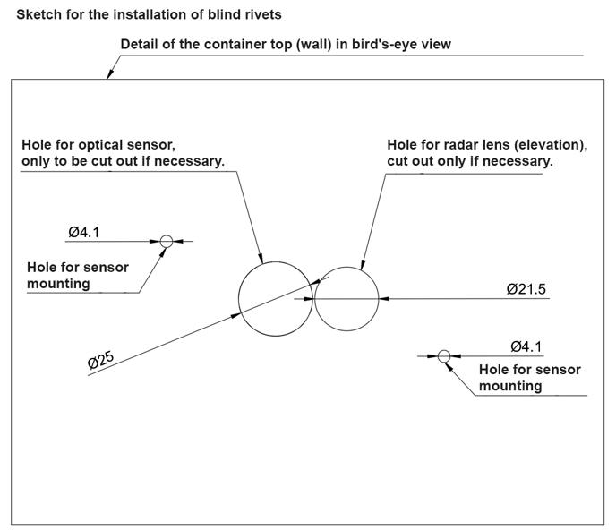
The holes for the blind rivets have a diameter of 4.1 mm.
Step 1: Depending on the sensor type (radar and ToF only), drill the appropriate holes in the wall where you want to mount the sensor . Use the drilling template for this. The holes for the blind rivets should have a diameter of 4.1 mm.
Step 2: Insert the rivets through the designated tabs. Use the included spacers (the longer version) for this. First, thread the blind rivets through the spacers and then through the tabs on the sensor. Now rivet the blind rivets with a suitable tool.
.png?width=688&height=524&name=Untitled%20(63).png)
.png?width=688&height=499&name=Untitled%20(64)%20.png)
.png?width=688&height=400&name=Untitled%20(65).png)
Step 3: The sensor is now installed.
.png?width=688&height=380&name=Untitled%20(66).png)
20. Front-panel mounting with blind rivets
For this type of installation, always use the spacer plate to ensure the correct distance between the antenna and the wall .
Front-wall mounting is used when you want to mount the front of the Apollon-Q sensor on the wall of the building where the sensor is to be installed. The front side is the side with the opening in the center, where the logo is also visible.
Activate the sensor before beginning installation.
For this type of installation, 4x40 blind rivets are used. Installation is performed using a spacer plate.
The clamping range is 3 mm to 6 mm.
The holes for the blind rivets have a diameter of 4.1 mm.
Step 1: Depending on the sensor type (radar and ToF only) , drill the appropriate holes in the wall where you want to install the sensor. Use the drilling template for this. The holes for the blind rivets should have a diameter of 4.1 mm.
.png?width=688&height=592&name=Untitled%20(67).%20png)
Step 2: Insert the blind rivets through the designated tabs. Use the supplied spacers (the shorter ones) for this.
First insert the blind rivets through the spacers, then through the tabs on the sensor, and finally through the spacer plate.
Then rivet the blind rivets in place using a suitable tool.
.png?width=688&height=519&name=Untitled%20%20(68).png)
-png.png?width=688&height=377&name=Untitled%20(69)-png.png)
.png?%20width=688&height=253&name=Untitled%20(70).png)
Step 3: Now install the sensor.
.png?width=688&height=351&name=Untitled%20(71).%20png)
21. Hall Switch Magnetic Switch Installation Instructions
The sensor features two Hall sensors (magnetic field switches). The following diagram shows the location of the Hall sensors and the recommended placement of the magnets.
%20.png?width=506&height=351&name=Untitled%20(72).png)
- Both magnetic field switches are active. Either one or both sensors can be used.
- Large neodymium magnets are recommended. These should be mounted as close as possible to the sensor. A recommended distance between the magnet and the sensor cannot be universally specified due to the variable size of the magnet. A maximum distance of 1 cm between the magnet and the housing is recommended.
- For comparison: With a neodymium disc magnet with d = 20 mm and h = 5 mm, reliable readings are achieved at distances under 1 cm.
- The magnetic field switches can be operated in three different modes :
- The container is closed when the magnet is in contact.
- The container is open when the magnet comes into contact.
- The sensor counts an opening when the magnet passes through twice.
22. NFC Setup and Location of the NFC Tag Activation is performed via an NFC app.
-
Activation is performed via an NFC app. This requires a
smartphone. The app can be downloaded from the respective app stores
. Simply search for
"Sentinum LinQs" and download the LinQs app.
.png?width=688&height=331&name=Untitled%20(29).png)
Figure 40. Downloading the Sentinum LinQs app -
First, place the tag on the sensor, and then place the
reader on your device. You can find the position of the NFC tag
in the following figures.
.png?width=688&height=386&name=Untitled%20(74).png)
Figure 41. Position of the NFC tag on the sensor -
Open the app and activate the sensor. To start the sensor
in the basic settings, click the
button "Activate Sensor" button. Now place
your device on the sensor's NFC tag.
.png?width=688&height=275&name=Untitled%20(26).png)
Figure 42. Activating the sensor via the LinQs app - When the sensor is activated, "Sensor updated!" is displayed. You can then proceed to activate the other sensors.
23. Replacing the Battery
-
Open the housing using a special Torx screwdriver.
Carefully remove the cover and make sure
that the seal is not damaged.
.png?width=688&height=507&name=Untitled%20(75).png)
Figure 43. Opening the housing to replace the battery -
Now carefully remove the cells from the designated
holder and insert the new cells. To achieve the
runtimes and performance specified in the
data sheets, the following primary cells are permitted:
a. For LoRaWAN® and mioty® sensors
- Energizer® Ultimate Lithium batteries - AA
- VARTA ULTRA LITHIUM Mignon AA
b. For cellular sensors (NB-IoT and LTE-CAT-M1)
- VARTA-CR-AH-R
Each sensor requires 2 cells..png?width=688&height=524&name=Untitled%20(76).png)
Figure 44. Replacing the battery cells - Once the replacement is complete, please dispose of the old cells properly. Then screw the housing back together. Make sure that the original position of the gasket has not been altered.
If cells other than those recommended are used, performance and product safety may be compromised.