1. Version History
| Version | Date | Revision |
|---|---|---|
| 1.0.0 | January 6, 2023 | Created |
| 1.0.1 | April 9, 2026 |
Structure standardized
Downlink clarified Content updated |
2. Downlinks
This documentation can be used for all sensors in the Sentinum series that support NFC and downlink functions. It serves as generic documentation. Individual descriptions of the fields can be found in the respective sensor-specific documentation.
All downlinks for the sensor and LoRa module are terminated on Port 4. All commands that execute a function, such as resets, are terminated on Port 5.
Like the payload, the downlink commands are also divided into modules. The sensor merely acts as a container that manages and executes the commands. The downlinks can be used to configure the sensor for the respective application. In addition to configurations, executable downlinks such as a reset can also be performed. All commands are protected by minimum and maximum values.
- Module
- Group
- Resource
- Command
A module has several groups, which in turn consist of several resources.
3. Overview of the ports for the downlink
| Port | Channel | Description |
|---|---|---|
| 0 | Uplink | Join |
| 1 | Uplink | Telemetry Uplink |
| 2 | Uplink | Information Uplink |
| 3 | Uplink | Response to a downlink |
| 4 | Downlink | Port for downlinks to configure settings |
| 5 | Downlink | All commands marked with EXEC, e.g., Supervisor Module, Reboot, Reset, or Start Scan |
| 6 | Downlink | Downlink command for reading configurations |
| 192 | Uplink | GNSS scan data |
| 197 | Uplink | Wi-Fi SSID scan data |
4 for configuration, Port 5 for executable commands, Port 6 for reading current configurations.
4. Modules and Groups – Example Overview
| Module | Module Key | Group | Group ID | Description |
|---|---|---|---|---|
| Juno | 0x1XXX |
Alarm Settings & Timing | 0x00 |
Defines parameters for alarm settings, measurements, and transmission behavior |
| Juno | 0x1XXX |
ToF Sensor Settings | 0x01 |
Defines measurement parameters for the ToF sensor |
| Juno | 0x1XXX |
Radar Sensor Settings | 0x02 |
Defines measurement parameters for the radar sensor |
| Juno | 0x1XXX |
Opening Detection Settings | 0x03 |
Defines measurement parameters for the opening counter |
| Juno | 0x1XXX |
Vandal Detection Settings | 0x04 |
Defines measurement parameters for vandalism detection |
| LoRa | 0x2XX1 |
Network Settings | 0x00 |
Network Management Settings |
| LoRa | 0x2XX1 |
Transmission Settings | 0x01 |
Transmission Parameters and Protocol Settings |
| LoRa | 0x2XX1 |
Rejoin Settings | 0x02 |
Parameters for Link Check |
5. Important points regarding downlinks
- All configuration commands for sensor and LoRa modules are executed on port
4, all execution commands on port5. - Sentinum guarantees backward compatibility across different subversions. A Sentiface/Sensor module with the key
0x1121also accepts downlink commands with the key0x1111. - The actual value communicated to the sensor via downlink is always 4 bytes, except for command messages (executables). In those cases, the message size varies.
- A downlink is always acknowledged with an additional uplink as a response.
- Starting with version
0x22XX, current parameters can be queried via downlink. No configuration value is sent along with this. The downlink must be sent on port6; the response is sent on port3.
Example for reading the current ADR value:
11 22 11 01 02
6. Structure of the module key
Structure of the module key
| Byte | Bit range | Meaning |
|---|---|---|
| Byte 1 | Bits 7–4 | Base ID, e.g., Sensor, LoRa, or Sentivisor |
| Byte 1 | Bits 3–0 | Major version (SW/HW version) |
| Byte 2 | Bits 7–4 | Minor version (SW/HW version) |
| Byte 2 | Bits 3–0 | Product version (mounted sensors) |
The module key of the sensor module can be derived from the first two bytes of each uplink.
- The module key explained here applies only to the sensor module. For the LoRa module, always use
0x2XXXas the module key. - In addition to the downlinks, there is an app for the initial configuration of the sensor. The NFC interface offers additional configuration options, such as for APPEUI or APPKEY.
General downlink structure
| Byte | Designation | Description |
|---|---|---|
| Byte 0 | Token | Used to assign a confirmation to a previously sent command. Can be freely chosen. |
| Bytes 1 to 2 | Module key | Describes the specific version of the sensor and selects the module. |
| Byte 3 | Group | Selects the group to which the command is assigned. |
| Byte 4 | Resource | Selects the resource ID within the group. |
| Bytes 5 through 8 | Value | Contains the new resource value. |
Example downlink:
0x01 0x1111 0x03 0x00 0x00 00 10 00
7. Commands to Execute – Executables
Downlink commands can be scheduled in the network server. These do not have a configurable value, meaning the last four bytes for value setting are omitted. Executable commands are assigned to the respective groups.
The following example simplifies the GNSS group of a Juno sensor.
| Resource | Resource ID | Description | Module Key |
|---|---|---|---|
| GNSS MODE | 0x00 |
Order of localization technologies: 0 Off, 1 GNSS Scan, 2 Wi-Fi SSID Scan, 3 GNSS then Wi-Fi, 4 Wi-Fi then GNSS | 22XX |
| GNSS UPDATE PERIOD | 0x01 |
Localization update period in hours | 22XX |
| DOWNLOAD ALMANAC DATA | 0x02 |
0: Do not download data, 1: Download almanac data | 22XX |
| GNSS IN MOBILE APPLICATIONS | 0x03 |
0: optimized for static objects, 1: optimized for moving objects | 22XX |
| PERFORM SCAN | 0x04 |
Start scan. Example downlink on port 5: 11 2211 03 04 |
22XX |
8. Glossary for the Documentation
| Term | Explanation |
|---|---|
| Group ID | An ID that allows the user to modify various resources within a configuration unit. |
| Resources | Individual modifiable elements responsible for the configuration and customization of a system. |
| Resource ID | An identifier that distinguishes between different configuration options of a system. |
| Key | An NFC/BLE key for authentication and access control to resources within a system. |
| Min / Max | Minimum / Maximum |
| Module Key | A key that enables access to a specific configuration unit within a system. |
Additional Glossary
| Term | Explanation |
|---|---|
| green / yellow / red | The focus is not on color accuracy, but on the variety of shades of green/orange, yellow, and amber/red tones, although the colors may vary depending on the product. |
| Default (old) | Used as a synonym for factory setting. |
9. Sensor Settings – Apollon-Q Example
9.1. Sensor: Timings and Alarms Group 0x00
| Resource | Resource ID | Description | Min | Max | Default | Unit | Module key |
|---|---|---|---|---|---|---|---|
| MEASUREMENT PERIOD | 0x00 |
Sets the time period during which measurement values are recorded. | 5 | 660 | 60 | 1111 | |
| DELTA VALUE | 0x01 |
Absolute value by which the level must change since the last transmission in order to trigger an alarm transmission. | 30 | 2000 | 200 | 1111 | |
| TRANSMISSION INTERVAL | 0x02 |
Number of measurements after which the sensor schedules an uplink despite the absence of an alarm condition. | 1 | 10 | 1 | dr | 1111 |
| MASTER VALUE | 0x03 |
Specifies which sensor value is written to the master_value parameter: 0 ToF, 1 Radar. |
0 | 1 | 0 | 1111 |
9.2. Sensor: ToF Sensor Settings Group 0x01
| Resource | Resource ID | Description | Min | Max | Default | Unit | Module Key |
|---|---|---|---|---|---|---|---|
| ToF RANGING MODE | 0x00 |
0 automatic, 1 fixed. In automatic mode, the sensor selects between short, medium, and long. | 0 | 1 | 0 | 1111 | |
| ToF RANGE INDEX | 0x01 |
0 short, 1 medium, 2 long. | 0 | 2 | 1 | 1111 | |
| ALGORITHM APPLIED | 0x02 |
0 No histogram, 1 Histogram, 2 Hybrid. | 0 | 2 | 2 | 1111 |
9.3. Sensor: Opening Detection Group 0x03
| Resource | Resource ID | Description | Min | Max | Default | Unit | Module Key |
|---|---|---|---|---|---|---|---|
| OPENING DETECTION COOLDOWN | 0x00 |
Time period during which no further opening can be triggered after an opening has been triggered. | 1 | 600 | 120 | 1111 | |
| OPENING DETECTION ALARM AFTER | 0x01 |
Time the cover must remain open before an alarm is triggered. | 60 | 3600 | 900 | 1111 | |
| OPENING DETECTION SOURCE | 0x02 |
0 None, 1 Accelerometer, 2 Hall Switch. | 0 | 2 | 0 | 1111 | |
| OPENING DETECTION HALL SWITCH | 0x03 |
0 Container closed when solenoid is activated, 1 Container open, 2 Sensor detects an opening when the sensor is triggered twice. | 0 | 2 | 0 | 1111 | |
| OPENING DETECTION ACTIVE | 0x04 |
0 disabled, 1 enabled. | 0 | 1 | 0 | 1111 | |
| OPENED LID OR FLAP | 0x05 |
Specifies whether an alarm is triggered after the "Open Alarm After" time has elapsed if the container is open. | 0 | 1 | 0 | 1111 |
9.4. Sensor: Vandalism Detection Group 0x04
| Resource | Resource ID | Description | Min | Max | Default | Unit | Module Key |
|---|---|---|---|---|---|---|---|
| VANDALISM DETECTION ACTIVATED | 0x00 |
0 Vandalism detection off, 1 Vandalism detection on. | 0 | 1 | 0 | 1111 | |
| IMPACT DELTA | 0x01 |
Maximum time between two impacts for a vandalism alarm to be triggered based on the number of impacts. | 5 | 100 | 30 | sec | 1111 |
| IMPACT NUMBER | 0x02 |
Number of impacts, of which no more than two may fall within Impact Delta. | 3 | 100 | 5 | 1111 | |
| IMPACT STRENGTH | 0x03 |
A hit is counted when the acceleration exceeds the set impact strength value. | 500 | 2000 | 1000 | Mg | 1111 |
| COOLDOWN | 0x04 |
The time period during which no further vandalism alarm can be triggered after a vandalism alarm has been triggered. | 10 | 1440 | 30 | min | 1111 |
9.5. Sensor: Value Retransmission Group 0x05
| Resource | Resource ID | Description | Min | Max | Default | Unit | Module Key |
|---|---|---|---|---|---|---|---|
| TRANSMIT PAST READINGS | 0x00 |
Transmit past readings: 0 off, 1 on. | 0 | 1 | 1 | 1111 | |
| NUMBER OF PAST READINGS | 0x01 |
Number of past readings transmitted in a packet. | 1 | 15 | 10 | 1111 |
10. Examples
First, let's configure our sensor. We decide to set the sensor to acknowledged mode. To do this, we look at the following downlink (HEX code):
9.1. Setting Confirmed Mode
Example downlink for activating confirmed mode.
01 21 11 01 00 00 00 00 03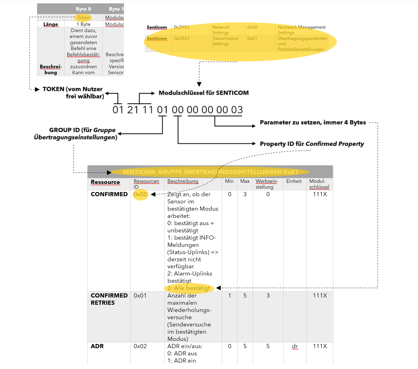
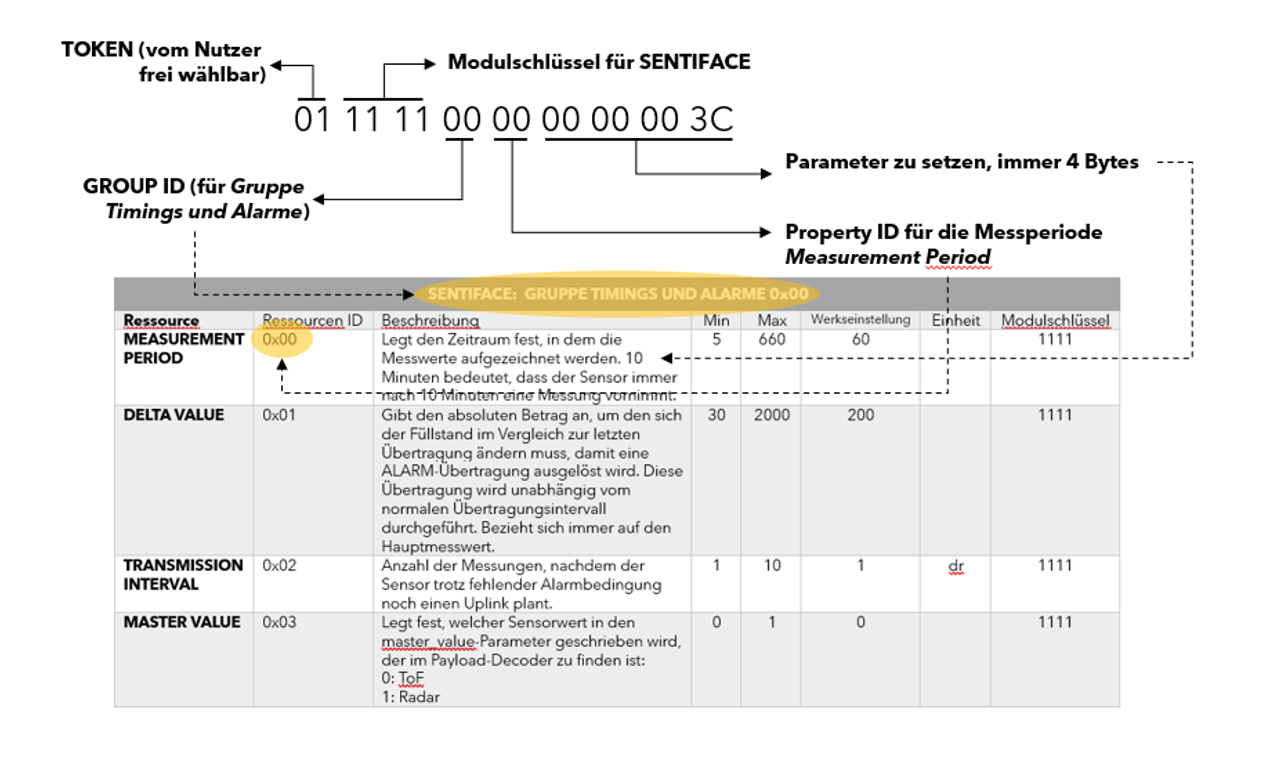
9.2. Change the measurement interval to 24 times per day
Example downlink for a 60-minute interval.
01 11 11 00 00 00 00 00 3C