1. Version History
| Version | Date | Change |
|---|---|---|
| 1.0.0 | June 2, 2025 | Created |
| 1.0.1 | March 25, 2026 |
|
2. Overview
The Hyperion Energy Meter (Sentinum) transmits energy data via the MIOTY protocol. This document describes the payload structure, profiles, and field definitions (starting with firmware v1.3).
Device Info:
- Type EUI:
FCA84A0000000006 - Vendor: Sentinum
- Protocol: mioty
- Firmware: v1.3+ (Payload only if
fw_minor_ver ≥ 3andstatus = 0)
3. Configuring Profiles
| Profile | Setting/Value |
|---|---|
| 0 | 000 |
| 1 | 001 |
| 2 | 002 |
| 3 | 003 |
| 4 | 004 |
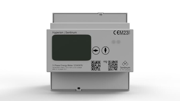
Familiarize yourself with the display.
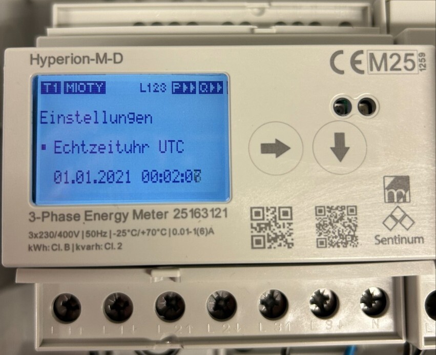
3.1. Step 1: Mioty DEVEUI
Use the down arrow key to scroll to the "Mioty DevEUI Settings" section, as shown on the screen. Here you will see the device number.
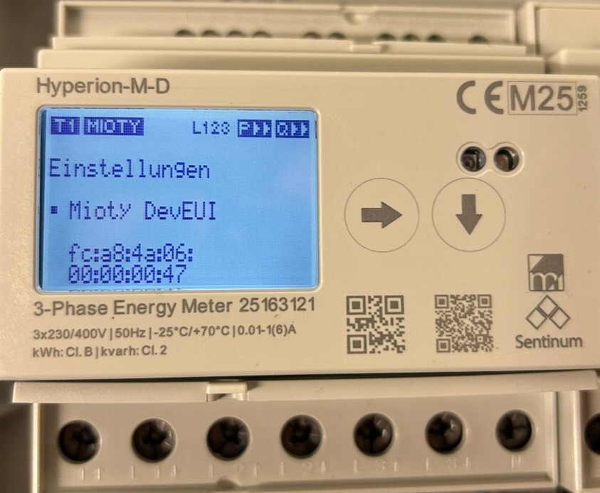
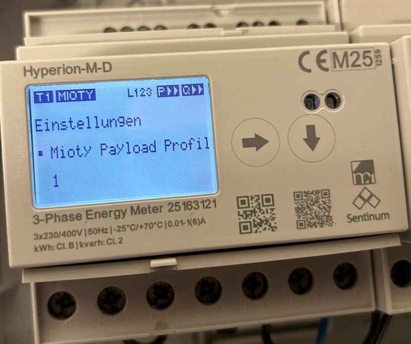
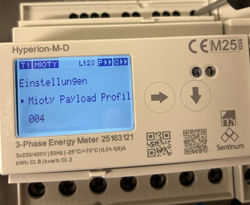
3.2. Step 2: Navigate to Mioty Payload Profile
Use the down arrow key to navigate to "Mioty Payload Profile Settings." The number at the bottom indicates the selected payload profile.
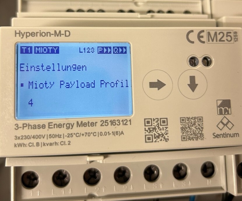
3.3. Step 3: Changing the Profile
Using an insulated screwdriver, press the button on the lower right, as shown in the image. The number will then be displayed as a 3-digit value, e.g., 001. Use the right button to navigate through the decimal places, and the down button to adjust the respective digit (increment).
Note: The profile must always be specified in the following format: 001 or 004, etc. Even if the meter can be set to a code of 009, for example, this is not a valid profile. A 0 can be reached again by counting the digit up to 9; after that, the digit jumps back to 0. Please set only profiles 000 through 004.
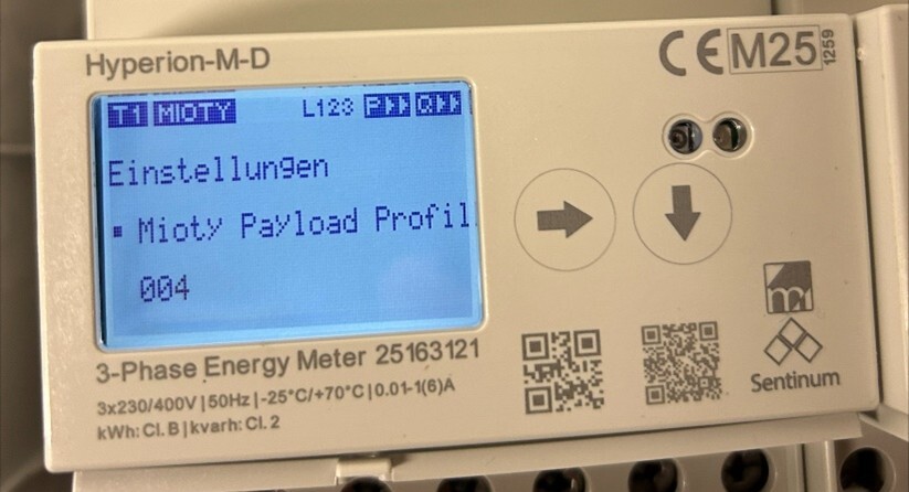
In the following image, 004 has been set.
3.4. Step 4: Confirm the profile
To change the profile, please press and hold the button on the back right with an insulated pin or screwdriver until the display and keypad flash briefly.
4. Payload Structure
| Field | Size | Type | Description |
|---|---|---|---|
fw_base_id | 4-bit | uint | Firmware base identifier |
fw_major_ver | 4-bit | uint | Major version |
fw_minor_ver | 4-bit | uint | Minor version |
dev_sub_type | 4-bit | uint | Device subtype |
msg_counter | 8 bits | uint | Uplink counter |
status | 8-bit | uint | Device status (0 = normal) |
serial_num | 32-bit | uint | Serial number |
app_version | 32-bit | uint | Application version |
mid_version | 32-bit | uint | Middleware version |
profile | 32-bit | uint | Profile selector (0–4) |
5. Naming Conventions
- Voltage:
u_lX(phase/line) - Current:
i_lX(phase/total) - Power:
p_lX_a(active, phase/total) - Energy:
e_t{a|1|2}_{a|r}_{i|e}(e.g.,e_ta_a_i) - Power Factor:
pf_lX - Frequency:
f - Transformer ratio:
{ct|vt}_{act|old}_{prim|sec}
6. Transmission frequencies
| Profile | Transmission frequency (min) |
|---|---|
| 0 | 5 |
| 1 | 2 |
| 2 | 2 |
| 3 | 2 |
| 4 | 15 |
7. Factory Setting
Profile 0 is used as the factory setting (see 8).
8. Profiles
8.1. Profile 0 – Complete data
Comprehensive measurement values: power, current, voltage, energy, power quality.
- Power (W):
p_l1_a,p_l2_a,p_l3_a,p_l123_a - Current (mA):
i_l1,i_l2,i_l3,i_l123 - Voltage (V ÷10):
u_l1,u_l2,u_l3,u_l12,u_l23,u_l31 - Energy (Wh):
e_ta_a_i,e_ta_a_e,e_ta_r_i,e_ta_r_e - Power Quality:
pf_l1–3(÷100),f(Hz ÷10) - Status:
pwr_fail
8.2. Profile 1 – Voltage & Current
Focus on voltage and current values with power quality.
- Voltage (V ÷10):
u_l1,u_l2,u_l3,u_l12,u_l23,u_l31 - Current (mA):
i_l1,i_l2,i_l3,i_l123 - Power Quality:
pf_l1–3(÷100),f(Hz ÷10)
8.3. Profile 2 – Power & Current
Focus on active power, currents, and power quality.
- Power (W):
p_l1_a,p_l2_a,p_l3_a,p_l123_a - Current (mA):
i_l1,i_l2,i_l3,i_l123 - Power Quality:
pf_l1–3(÷100),f(Hz ÷10)
8.4. Profile 3 – Energy Meter
Minimal payload for billing & monitoring.
- Energy (Wh):
e_ta_a_i,e_ta_a_ee_ta_r_i,e_ta_r_e
8.5. Profile 4 – Historical Data
Extended profile, including timestamps, rates, and CT/VT configuration (Little-Endian).
- Time/Index:
index,epoch,epoch_old - Energy by rate (Wh):
- T1:
e_t1_a_i/e,e_t1_r_i/e - T2:
e_t2_a_i/e,e_t2_r_i/e
- T1:
- Currents (mA):
i_l1–4,i_l123 - Power (W):
p_l1_a,p_l2_a,p_l3_a,p_l123_a,p_l123_a_avg - Voltage (V ÷10):
u_l1,u_l2,u_l3 - Power Quality:
f(Hz ÷10),pf_l1–3(÷10) - CT/VT configuration:
ct_act_prim/sec,ct_old_prim/sec,vt_act_prim/sec,vt_old_prim/sec
9. Data Encoding
| Component | Size | Type | Scale | Unit | Description |
|---|---|---|---|---|---|
| Voltage | 32-bit int | int | ÷10 | V | Phase/line voltages |
| Current | 32b int | int | 1:1 | mA | Phase/Total current |
| Power | 32b int | int | 1:1 | W | Active power |
| Energy | 64b uint | uint | 1:1 | Wh | Meter readings |
| Power Factor | 8b int | int | ÷100 (÷10 for LE) | – | -1.0 … +1.0 |
| Frequency | 16-bit int | int | ÷10 | Hz | Mains frequency |
| Timestamp | 64b uint | uint | 1:1 | s | Unix epoch |
| CT/VT Ratio | 16-bit uint | uint | 1:1 | – | Transmission Ratios |
10. Usage Notes
Profile selection:
- Profile 0 = Full monitoring
- Profile 1 = Voltage quality
- Profile 2 = Power analysis
- Profile 3 = Billing
- Profile 4 = Historical data
Example .js:
const voltage = raw_u_l1 / 10; // 2350 → 235.0 V
const pf = raw_pf_l1 / 100;   // -85 → -0.85
const net_energy = e_ta_a_i - e_ta_a_e;
const ct_ratio = ct_act_prim / ct_act_sec;
11. Compatibility and Notes
- Firmware version 1.3 or higher required
- Payload only if
fw_minor_ver ≥ 3andstatus = 0 - All fields are visible; no hidden fields
- Ensure correct endianness
- Optimize profiles Payload size depending on use case
- Profile 4 enables time series analysis with epoch timestamps
Specifications subject to change without notice. All information provided without guarantee.
![]()
![]()
![]()

