1. Warnings and safety instructions
Warnings and important information about potential hazards or damage
Important information required for smooth operation of the devices
Please note:
- Follow the safety instructions and installation guidelines in this manual and the mounting list.
- Ensure that the installation environment complies with the specified operating conditions. Always observe temperature and other limits.
- The device may only be used within the technical specifications.
- The device may only be used for its intended purpose.
- Safety and functionality can no longer be guaranteed if the device is modified or altered.
- The purpose of the sensor is to monitor indoor air quality.
- Do not use the sensor in safety-critical applications!
- The sensor is expressly not suitable for monitoring carbon monoxide CO!
- The sensor is not a smoke detector!
- Do not mount the sensor on ceilings or floors.
- The device is approved for operation up to a maximum of 2000 meters above sea level.
- A minimum distance of 20 cm between the device and persons must be maintained.
If the device is installed incorrectly:
- It may not function properly.
- It could be permanently damaged.
- It could pose a risk of injury.
Please note during handling and disposal:
- The sensor must not be opened!
- Improper handling such as improper mechanical stress, e.g. dropping the device, may result in damage.
- Dispose of in accordance with local regulations for waste electrical and electronic equipment.
- Contains a lithium battery (UN38.3 compliant) - do not dispose of in fire, do not disassemble or short-circuit.
- The secondary cell is a supercapacitor - do not damage or dispose of improperly.
- Dispose of batteries and rechargeable batteries separately in accordance with the relevant recycling regulations.
- Environmentally friendly disposal by returning to authorized collection points is recommended.
- Do not dispose of in household waste
Please note CO₂ sensor:
- The CO₂ measuring module is particularly sensitive to mechanical stress. A fall, even from a low height, as well as shocks and impacts can damage the device. This can lead to incorrect measurements.
2. Further documentation
Please note the information and limit values in the technical data sheet.
The Sentiface sensor-specific documents can be found in the NFC and downlink description document, the Senticom and Sentivisor tables can be found in the generic NFC and downlink documentation. The option for configuring sensor communication can be found in the respective generic LoRaWAN® or Mioty® documentation, depending on the version.
Further generic documentation can be found at: https://docs.sentinum.de/en/important-cross-product-documentation-for-sensors
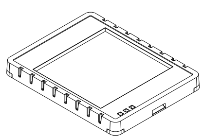
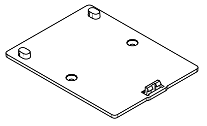
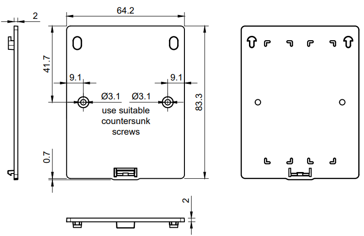
3. Technical Drawing
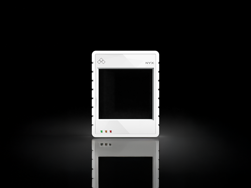
Nyx sensor
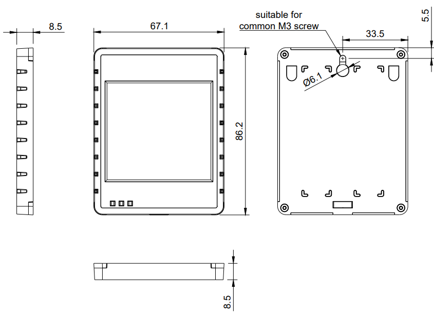
Wall bracket
4. Description of important components and scope of delivery
- 1× Nyx sensor
- 2× adhesive strip for wall mount
- 1× wall bracket
5. Assembly and installation
If the sensor is still easily accessible after installation, install the sensor first and activate it after installation!
If the sensor is no longer accessible after installation, first activate the sensor and then install it after activation!
| Mounting method | Recommended accessories |
|---|---|
| Wall bracket (screws) | 2× M3 countersunk screws |
| Wall bracket (adhesive strips) | 2× adhesive strips |
Please note:
- Do not insert any objects or body parts into the ventilation slots of the sensor.
- Do not mount the sensor on the ceiling or floor.
- Do not install the sensor at heights above two meters.
- Only install the sensor indoors on a wall in a standard room at a height of 1.50m to 1.80m.
- Install the sensor in a location that receives at least 7 hours of direct sunlight at 400lux per day to ensure optimum energy supply.
- Make sure that the LEDs are on the lower left-hand side when mounting.
5.1 Attaching the wall bracket with screws
Please note: Before using this type of installation, make sure that the surface to which the wall bracket is to be screwed is flat and has a base suitable for the material in order to prevent damage to the housing.
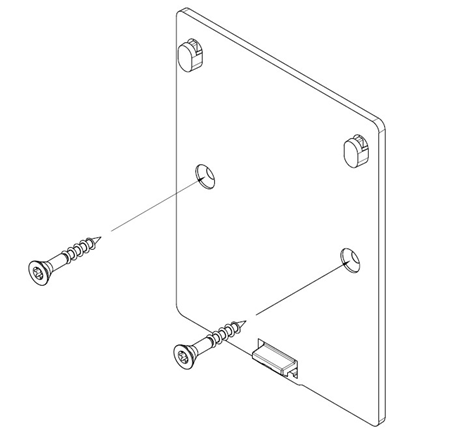
Screw the wall bracket into the wall with two M3 countersunk screws as shown in the picture. The snap lock is at the bottom and points away from the wall. Once the bracket is attached, check that it is secure by gently shaking it. If the bracket is not stable, check the screws and tighten them if necessary. Once the bracket is securely attached to the wall, you can continue with step 5.3.
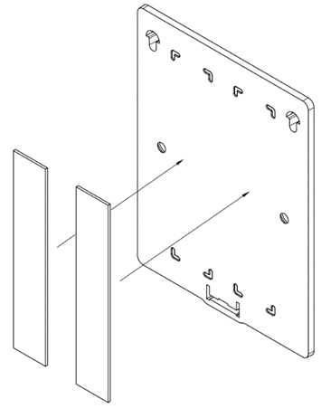
5.2 Attaching the wall bracket with adhesive strips
Please note:
- Before using this installation method, make sure that the surface is clean, dry, smooth and adhesive, as an uneven or dusty surface can impair the adhesion of the adhesive strips.
- Avoid mounting on rough, porous or damp surfaces, as this can reduce the adhesive strength and cause the mount to peel off.
- Press the mount firmly for a few seconds after application to ensure an optimum bond between the adhesive strips and the surface.
Stick the wall bracket to the wall in the marked area using the two double-sided adhesive strips, as shown in the picture. The snap lock is at the bottom and points away from the wall. Once the bracket is attached, check that it is secure by pulling gently on it. Make sure that the adhesive strips adhere completely and that no corners come loose. Once the bracket is securely attached to the wall, you can continue with step 5.3.
5.3 Mounting the sensor on the wall bracket
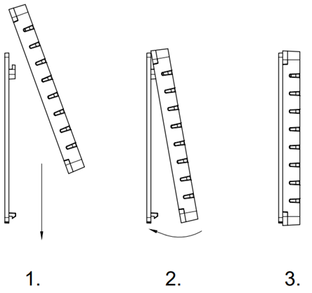
- Insert the sensor into the wall bracket from above until it snaps into the upper bracket
- Tilt the sensor backwards so that it snaps securely into the bracket and the snap lock
- Ensure that the sensor is fully seated in the bracket and is firmly attached.
6. Commissioning and use
Please note that the housing or electronics may be damaged if knives or other sharp objects are used.
6.1 Commissioning the sensor
The sensor is supplied ready for operation and switched on.
6.2 NFC parameterization and position of the NFC tag
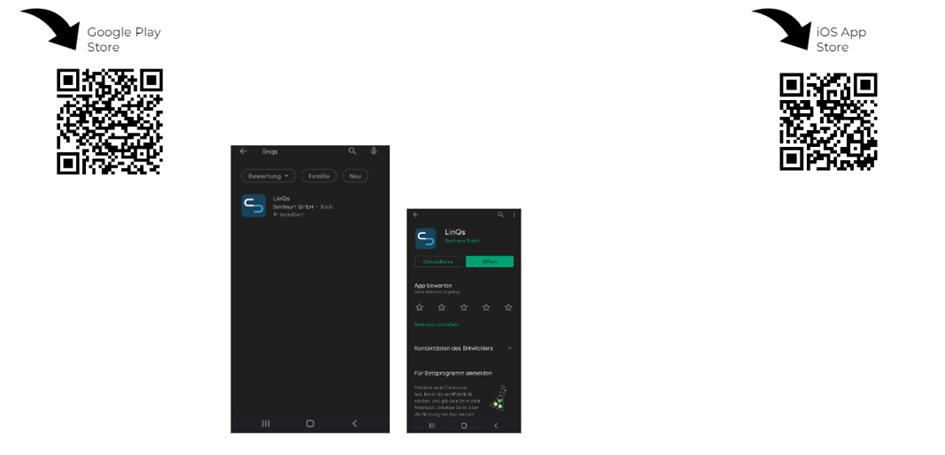
Activation takes place via an NFC app. A smartphone is required for this. The app can be downloaded from the respective app stores. Simply search for "Sentinum LinQs" and download the LinQs app.
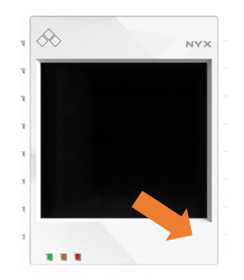
First locate the tag on the sensor and then the reader on your end device. You will find the location of the NFC tag at the following position:
6.3 Intended use of the sensor
The solar-powered IoT sensor with CO₂ and humidity detection is ideal for monitoring indoor air quality and environmental conditions. By combining a CO₂ sensor and a humidity sensor, the sensor provides precise data on important environmental influences and is energy self-sufficient thanks to an integrated solar panel. This sensor is particularly suitable for the following applications:
- Optimizing indoor air quality: the CO₂ sensor continuously measures the CO₂ concentration and ensures a healthy and comfortable indoor climate. In public and commercial buildings as well as in indoor spaces with high human traffic, the sensor helps to detect high CO₂ values and enable timely ventilation.
- Humidity monitoring:The humidity sensor records the moisture content of the air and ensures that climatic conditions remain optimal. Humidity levels that are too high can encourage mold growth, while levels that are too low can affect the health or well-being of plants.
- Energy-efficient operation:Thanks to the solar panel, the sensor is self-sufficient and does not require an external power source. This makes it particularly suitable for use in areas without power sockets, while at the same time minimizing energy consumptions.
- Customizable settings: The sensor offers the user the option of specifying individual settings for CO₂ and humidity values. This means that specific threshold values for alarm functions and notifications can be adapted to the user's own needs and requirements. This enables even more precise control and ensures that the sensor is optimally adapted to the respective operating conditions.
- Use in smart building systems: The sensor can be easily integrated into existing ventilation, heating and air conditioning systems. The data collected on CO₂ and humidity enables needs-based and energy-efficient control, which increases user comfort and reduces operating costs.
- Compliance with environmental standards: The sensor helps to meet air quality specifications in public buildings, schools or care facilities by enabling continuous monitoring of indoor air.
- Notifications and remote monitoring: The sensor uses Long Range Wide Area Network communication to transmit data in an energy-saving way and to send notifications if critical values are exceeded. This means that environmental conditions can be monitored remotely and action can be taken quickly if necessary, without the need for permanent real-time monitoring.
With this sensor, environmental influences can be monitored efficiently and measures can be taken to improve air quality and the indoor climate - with minimum energy consumption and maximum efficiency.
7. Behavior of the LoRaWAN interface and joining
Information on setting up LoRaWAN can be found in the generic document here: Generic LoRaWAN® documentation.
8. Care and cleaning
To ensure that the sensor functions reliably and has a long service life, it should be maintained regularly. Please observe the following instructions:
- Regularly remove dust and dirt from the solar panel to ensure optimum energy absorption. Use a soft, clean microfiber cloth for this purpose. A slightly moistened cloth can be used for stubborn dirt - however, avoid using cleaning agents or abrasive cleaners.
- Clean the housing, especially the ventilation slots of the sensor, with a dry or slightly damp microfiber cloth. Make sure that no moisture penetrates the device.
- Carry out cleaning regularly, especially in dusty or pollen-rich environments, to ensure the long-term functionality of the sensor.
- Regularly check that the sensor and the bracket are firmly seated.
- Do not use cleaning agents containing alcohol or solvents, as these can damage the surface of the sensor.
9. Labeling and certification