![Logo_quer_farbig.png]](https://docs.sentinum.de/hs-fs/hubfs/Logo_quer_farbig.png?height=40&name=Logo_quer_farbig.png)
- Payload Description
- Example of a Wi-Fi SSID scan payload
- Apollon Q T/R/TR/SW Payload Description
- Apollon Q T Version Payload Description (without radar)
- Apollon Q R Version Payload Description (without ToF)
- Apollon Q TR / SW Version Payload Description (with Radar and ToF)
- Apollon Q Appended Bytes (ACC / HALL)
- Apollon Q Bytes (Histogram Debug Data)
- Decoding Examples
1. Payload Description
This chapter describes the structure of the telemetry data. The number of bytes within the payload depends on the specific sensor configuration. The data structure is determined by which sensors and functions are present in the product.
Each payload begins with a header. This header contains information on the hardware and software versions, the current device status, and a master measurement value. The master measurement value can generally be interpreted as the sensor's current primary measurement value.
Depending on the sensor configuration, the header is followed by additional payload sections. These contain additional information on the measurement principles, position data, or functions for opening and event detection. Not every product variant includes all additional payload sections.
Payload Field Description
| Term | Description |
|---|---|
| Byte No. | Byte number starting at 1 |
| Alias | Human-readable name of the variable |
| Description | Description of the variable |
| Label | Label in the data converter or payload decoder |
| Unit | Unit of the variable |
| Datahub .json key | Key in the JSON object when using the Datahub |
Structure of the Module Key
| Byte 1 | Byte 2 | ||
|---|---|---|---|
| Bits 7–4 | Bits 3–0 | Bits 7–4 | Bits 3–0 |
| Module base ID (e.g., Sentiface, Senticom, Sentivisor) | Major Version (Software/Hardware Version) | Minor version (software/hardware version) | Product version (e.g., TH, THL, ACC, Radar) |
The module key for the Apollon-Q module can be derived from the first two bytes of each uplink. The module key is required, among other things, for interpreting the payload and for downlink commands.
The module key for the SENTIFACE module can be extracted from the first two bytes of each uplink. The module key is required for the correct interpretation of the payload as well as for downlink commands.
Port Assignment for WiFi SSID Scan, GNSS Scan, and Standard Payload
| Feature | LoRaWAN port | Description |
|---|---|---|
| GNSS Scan Payload | 192 | Raw data such as satellite IDs, time information, and other GNSS measurements are transmitted to the geolocation backend. |
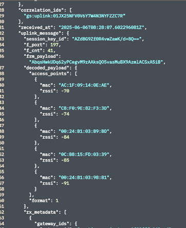
| Wi-Fi SSID Scan Payload | 197 | Detected MAC addresses and RSSI values are transmitted for position determination. |
| Regular Telemetry Data | 1 | Standard payload containing sensor data such as distance values, temperature, battery status, lid detection, or location information. |
2. Example of a Wi-Fi SSID scan payload
3. Apollon Q T/R/TR/SW Payload Description
| Byte Number | Alias Name | Unit | Description in the Decoder | Module Key | Datahub .json Key |
|---|---|---|---|---|---|
| 1 – 2 | Module key | – | module_key |
XXX1 |
module_key |
|
Description: Byte 1: • Module code (bits 7–4) • Major version (bits 3–0) Byte 2: • Minor version (bits 7–4) • Product version (bits 3–0) |
|||||
| 3 | Uplink counter | – | uplink_counter |
XXX1 |
uplink_counter |
|
Description: Protocol-independent uplink counter (0–255). |
|||||
| 4 – 5 | Battery voltage | mV | battery_voltage |
XXX1 |
battery_voltage |
|
Description: Current battery voltage in millivolts. |
|||||
| 6 | Internal Temperature | °C | internal_temperature |
XXX1 |
internal_temperature |
|
Description: Internal sensor temperature. |
|||||
| 7 | Alarm | – | alarm |
XXX1 |
alarm |
|
Description: Indicates whether an alarm has been triggered. |
|||||
| 8 – 9 | Master reading | mm | master_value |
XXX1 |
master_value |
|
Description: Main measured value of the sensor. |
|||||
For the subsequent bytes, please note the respective hardware version of the sensor (T, R, TR, or SW), as the payload structure may vary.
4. Apollon Q T Version Payload Description (without radar)
| Byte Number | Alias Name | Unit | Name in the Payload Decoder | Module Key | Datahub .json Key |
|---|---|---|---|---|---|
| 10 | ToF Sensor Status | – | tof_status |
XXX1 |
tof_status |
|
Description: Sensor status based on the last measured value. • 0: Valid range • 2 / 4: Out of bounds • 5: Hardware failure • 7: Target wrapped • 8: Algorithm failure • 14: Invalid range • 99: More than one valid target detected |
|||||
| 11–12 | Distance | mm | tof_distance |
XXX1 |
tof_distance |
|
Description: Currently measured distance by the ToF sensor in mm. (Compare with Master Value if the measurement source is identical.) |
|||||
| 13 | ToF Mode (Index) | – | tof_index |
XXX1 |
tof_index |
|
Description: The mode in which the sensor recorded the last value. • 0: Short (up to 1.3 m) • 1: Medium (up to 3 m) • 2: Long (up to 4 m) |
|||||
5. Apollon Q R Version Payload Description (without ToF)
| Byte Number | Alias Name | Unit | Description in Payload Decoder | Module Key | Datahub .json Key |
|---|---|---|---|---|---|
| 10 | Radar Status | – | radar_status |
XXX1 |
radar_status |
|
Description: • 0: Error • 1: Success |
|||||
| 11 | Number of peaks | – | radar_no_peaks |
XXX1 |
radar_no_peaks |
|
Description: Number of detected peaks. |
|||||
| 12–13 | Distance 1 | mm | radar_distance_1 |
XXX1 |
radar_distance_1 |
|
Description: Distance at maximum peak in mm. |
|||||
| 14–15 | Peak 1 | dBsm | radar_ra_1 |
XXX1 |
radar_ra_1 |
|
Description: Distance at maximum peak in dBsm. |
|||||
| 16–17 | Distance 2 | mm | radar_distance_2 |
XXX1 |
radar_distance_2 |
|
Description: Distance with the second-highest peak in mm. |
|||||
| 18–19 | Peak 2 | dBsm | radar_ra_2 |
XXX1 |
radar_ra_2 |
|
Description: Distance with the second-highest peak in dBsm. |
|||||
| 20–21 | Distance 3 | mm | radar_distance_3 |
XXX1 |
radar_distance_3 |
|
Description: Distance with the third-highest peak in mm. |
|||||
| 22–23 | Peak 3 | dBsm | radar_ra_3 |
XXX1 |
radar_ra_3 |
|
Description: Distance with the third-highest peak in dBsm. |
|||||
6. Apollon Q TR / SW Version Payload Description (with Radar and ToF)
| Byte Number | Alias Name | Unit | Designation in the Payload Decoder | Module Key | Datahub .json Key |
|---|---|---|---|---|---|
| 10 | ToF Sensor Status | – | tof_status |
XXX1 |
tof_status |
|
Description: • 0 – Valid range • 2 / 4 – Out of bounds • 5 – Hardware failure • 7 – Wrapped target • 8 – Algorithm failure • 14 – Invalid range • 99 – More than one valid target detected |
|||||
| 11 – 12 | Distance (see Master Value) | mm | tof_distance |
XXX1 |
tof_distance |
|
Description: Current measured distance from the ToF sensor in mm. |
|||||
| 13 | ToF Mode (Index) | – | tof_index |
XXX1 |
tof_index |
|
Description: • 0 – Short (up to 1.3 m) • 1 – Medium (up to 3 m) • 2 – Long (up to 4 m) |
|||||
| 14 | Radar Status | – | radar_status |
XXX1 |
radar_status |
|
Description: • 0 – Error • 1 – Success |
|||||
| 15 | Number of peaks | – | radar_no_peaks |
XXX1 |
radar_no_peaks |
|
Description: Number of detected peaks. |
|||||
| 16–17 | Distance 1 | mm | radar_distance_1 |
XXX1 |
radar_distance_1 |
|
Description: Distance at maximum peak in mm. |
|||||
| 18–19 | Peak 1 | dBsm | radar_ra_1 |
XXX1 |
radar_ra_1 |
|
Description: Distance at maximum peak in dBsm. |
|||||
| 20–21 | Distance 2 | mm | radar_distance_2 |
XXX1 |
radar_distance_2 |
|
Description: Distance with the second-highest peak in mm. |
|||||
| 22–23 | Peak 2 | dBsm | radar_ra_2 |
XXX1 |
radar_ra_2 |
|
Description: Distance with the second-highest peak in dBsm. |
|||||
| 24–25 | Distance 3 | mm | radar_distance_3 |
XXX1 |
radar_distance_3 |
|
Description: Distance with the third-highest peak in mm. | |||||
| 26–27 | Peak 3 | dBsm | radar_ra_3 |
XXX1 |
radar_ra_3 |
|
Description: Distance with the third-highest peak in dBsm. |
|||||
7. Apollon Q – Appended Bytes (ACC / HALL)
| Appended bytes | Alias Name | Unit | Designation in the Payload Decoder | Module key | Datahub .json Key |
|---|---|---|---|---|---|
| 1 | Sensor Status (ACC) | – | acc_status |
XXX1 |
acc_status |
|
Description: Returns the status of the accelerometer: • 0: OK • Other values: Error |
|||||
| 1 | Orientation (ACC) | – | acc_orientation |
XXX1 |
acc_orientation |
|
Description: Displays the sensor's orientation: • 0: Vertical (lying on its side) • 1: Face Up (lens facing the ceiling) • 2: Face Down (lens facing the floor) • 3: Error |
|||||
| 1 | Flap Opening (ACC) | – | acc_open |
XXX1 |
acc_open |
|
Description: Indicates whether the lid is still open after a defined time interval. |
|||||
| 1 | Openings Lifetime Counter (ACC) | – | acc_open_cnt |
XXX1 |
acc_open_cnt |
|
Description: Total number of openings over the entire lifecycle. |
|||||
| 1 | Vandalism Alarm (ACC) | – | acc_impact |
XXX1 |
acc_impact |
|
Description: Indicates whether a vandalism event is active: • 0: No vandalism event • 1: Vandalism event |
|||||
| 1 | Flap Opening (HALL) | – | hall_open |
XXX1 |
hall_open |
|
Description: Indicates whether a flap (with a sensor attached) is open: • 1: Open • 0: Closed |
|||||
| 1 | Openings Lifetime (HALL) | – | hall_open_cnt |
XXX1 |
hall_open_cnt |
|
Description: Total number of openings over the entire life cycle (Hall sensor). |
|||||
8. Apollon Q – Appended Bytes (Histogram Debug Data, ToF Version = 2)
| Appended Bytes | Alias Name | Unit | Designation in the Payload Decoder | Module key | Datahub .json key |
|---|---|---|---|---|---|
| 1 byte appended | Histogram Type/Version | – | histo_type |
XXX1 |
histo_type |
|
Description: Specifies whether only values from the histogram function are transmitted or whether values from the averaging algorithm are also transmitted. • 0: Histogram values only ( master_value or
tof_distance)• 1: Histogram values and values from the averaging algorithm |
|||||
| 1 byte appended | Histogram Status | – | tof_hist_stat |
XXX1 |
tof_hist_stat |
|
Description: For more detailed information, please contact the manufacturer. Applies to variants with histogram type/version = 0 (identified by the payload length plus 5 bytes). |
|||||
| 2 bytes appended | Histogram distance | mm | tof_hist_dist |
XXX1 |
tof_hist_dist |
|
Description: Distance in mm calculated using the histogram feature algorithm. In normal operation, these values should deviate only slightly from the usual distance values and can compensate for heavy contamination on the lens. |
|||||
9. Decoding Examples (Febris)
11 11 CE 14 8E 07 EE 1D 00 02 03 D6 01 D1 00
| Bytes | HEX | Description |
|---|---|---|
| 1 | 11 | Module Key |
| 2 | 11 | Module key |
| 3 | CE | Uplink Counter |
| 4 | 14 | Battery Voltage |
| 5 | 8E | Battery Voltage |
| 6 | 07 | Internal Temperature |
| 7 | EE | Internal temperature |
| 8 | 1D | Relative humidity |
| 9 | 00 | Dew point |
| 10 | 02 | Dew point |
| 11 | 03 | Air Pressure |
| 12 | D6 | Air Pressure |
| 13 | 01 | CO₂ |
| 14 | D1 | CO₂ |
| 15 | 00 | Alarm |