![Logo_quer_farbig.png]](https://docs.sentinum.de/hs-fs/hubfs/Logo_quer_farbig.png?height=40&name=Logo_quer_farbig.png)
- Safety Instructions
- Related Documents
- Intended Use
- Technical Drawing
- Recommended Mounting Methods
- Default Settings and Threshold Values
- Installation and Preparation
- Wall Mounting with Screws
- Magnetic Mounting
- Sensor Commissioning
- NFC Configuration and Location of the NFC Tag
- Battery Replacement
- Certification
Warnings and important information about potential hazards, malfunctions, or possible damage.
Important information for the proper operation, configuration, and installation of the device.
Important instructions for safe and trouble-free operation of the devices.
1. Safety Instructions
- Follow the safety instructions and installation guidelines in the manual and the installation checklist.
- Ensure that the installation environment complies with the specified operating range guidelines. Always adhere to temperature and other limit values.
- The device may only be used within the ranges specified in the technical specifications.
- The device may only be used for the intended purpose described.
- Safety and proper functioning can no longer be guaranteed if the device is modified or expanded.
-
The purpose of the sensor is to monitor indoor air quality.
- Do not use the sensor in safety-critical applications.
- The sensor is expressly not suitable for monitoring carbon monoxide (CO).
- The sensor is not a smoke detector.
- The sensor must not be mounted on ceilings or floors.
- Operation of the sensor is only permitted up to a maximum altitude of 2000 m above sea level.
- Due to human exposure regulations, a minimum distance of 20 cm must be maintained between the device and people.
If the device is installed incorrectly:
- it may not function properly.
- it may be permanently damaged.
- there may be a risk of injury.
- Improper handling, such as subjecting the device to heavy mechanical stress or dropping it, can cause damage.
- The CO₂ measurement module is particularly sensitive to mechanical stress. A fall, even from a low height, as well as shocks and impacts can damage the device and lead to measurement errors.
2. Additional Documentation
Please refer to the information and limit values in the technical data sheet .
3. Intended Use
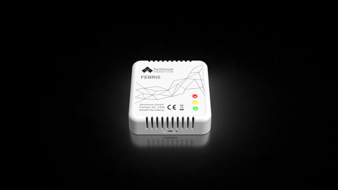
The Febris IoT Indoor Air Quality CO₂ Sensor is ideal for monitoring indoor air quality in spaces such as offices, conference rooms, stores, or public facilities. It measures CO₂ levels, providing important data on air quality and indoor climate. This information can be used to:
-
Ensure healthy indoor air: Excessively high CO₂ levels can lead to fatigue, difficulty concentrating, and discomfort. The sensor allows you to monitor CO₂ concentrations and indicates when to ventilate or turn on the air conditioning to ensure good air quality.
-
Improve energy efficiency: The sensor's data allows ventilation to be controlled as needed. Instead of maintaining a constant supply of fresh air (which consumes energy), ventilation can be activated only when it is truly necessary. This saves energy and reduces costs.
-
Creating conditions for high productivity: Good air quality is crucial for concentration and well-being. The sensor helps ensure optimal conditions, which promotes productivity and overall well-being in environments such as offices or classrooms.
-
Meeting regulatory requirements: Some countries have regulations or recommendations regarding maximum CO₂ levels in public buildings or workspaces. A CO₂ sensor helps ensure compliance with these standards and transparently demonstrates that measures are being taken to protect the health and comfort of occupants.
-
Enabling real-time notifications: With the Ferbis CO₂ sensor, measurement values can be read even over long distances. This allows building management to be notified immediately when critical CO₂ levels are reached and to intervene as needed.
4. Technical Drawing
-1.png?width=688&height=487&name=Untitled%20(1)-1.png)
-1.png?width=688&height=390&name=Untitled%20(2)-1.png)
5. Recommended Installation Methods
| Type | Recommended Accessories | Sentinum Part Number | Manufacturer |
|---|---|---|---|
| Screws (wall) | 3-pack anchors, SPAX 3 mm | Z-FEBR-SPAX | - |
| Magnets | Neodymium magnets with M4 internal thread | Z-FEBR-MAG-NEO | - |
| Adhesive | Double-sided adhesive tape | Z-FEBR-STRIPE | - |
6. Default Settings and Threshold Values
| Threshold Values | LED Behavior | Buzzer Behavior When Threshold Is Exceeded |
|---|---|---|
| 0 to 1000 ppm | Green LED | Two tones, first high, second low. The alert tone sounds when the system transitions to the green state, for example, from 1200 ppm to 800 ppm. |
| 1000 to 2000 ppm | Orange LED (Amber) | Two tones, first low, second high. The alert tone sounds, when the level changes to the orange state, for example, from 800 ppm to 1200 ppm or from 2200 ppm to 1800 ppm. |
| > 2000 ppm | Red LED | A double trill resembling a siren. The signal sounds when the device transitions to the red state, for example, from 1800 ppm to 2200 ppm. |
7. Installation and Preparation
If the sensor remains easily accessible after installation, install the sensor first and then activate it.
If the sensor is no longer accessible after installation, activate the sensor first and then install it.
- Before installation, make sure that the surface on which the sensor is to be mounted is level; otherwise, the housing may be damaged.
- Do not insert any objects or body parts into the ventilation slots of the sensor.
- Do not mount the sensor on the ceiling or floor.
- Do not mount the sensor at heights exceeding two meters.
The intended installation location for the sensor is in standard indoor spaces on a wall at a height of 1.50 m to 1.80 m. Use the sensor exclusively indoors and not outdoors. During installation, ensure that the LEDs are located on the lower right side.
8. Wall Mounting with Screws
- Open the housing at the snap-lock (see arrow) and remove the top cover. The PCB is secured with screws to the top cover.
- In step two, you will see the bottom of the sensor. For wall mounting, drill holes in the wall and insert suitable anchors. M3.5 screws conforming to DIN 7997 are recommended.
- If you are mounting the sensor on wood, the screws can be screwed directly into the wood. After the wall anchors have been secured, insert the screws through the designated openings in the rear panel of the housing. Alternatively, the two outer mounting eyelets can be used.
- Next, secure the bottom of the housing to the desired mounting location. For other mounting methods, DIN 7991 screws can also be used.
-1.png?width=381&height=313&name=Untitled%20(3)-1.png)
-1.png?width=415&height=578&name=Untitled%20(4)-1.png)
- Place the top of the sensor onto the attached bottom. Make sure the snap lock audibly clicks into place and that the correct installation orientation is maintained.
9. Magnet Installation
Permanent magnets can generate strong magnetic fields that can be dangerous if handled improperly. Therefore, observe the following warnings:
-
Protect your hands and fingers: Strong magnets can suddenly attract each other and pinch fingers or skin. This can lead to painful bruises and injuries. Always maintain a safe distance when handling permanent magnets and wear protective gloves if necessary.
-
Keep electronic devices away: Magnetic fields can damage electronic devices such as computers, smartphones, credit cards, pacemakers, and other sensitive electronics, or interfere with their operation. Therefore, always maintain a safe distance from such devices.
-
Beware of the risk of breakage: Many permanent magnets are made of brittle materials (e.g., neodymium) that can break if subjected to sudden impacts or excessive stress. The shards can be sharp and cause injuries. Therefore, handle the magnets with care and avoid impacts or excessive loads.
-
Health Risks: People with pacemakers or other implanted medical devices should avoid contact with strong magnets, as the magnetic fields can interfere with or deactivate these devices. Consult a doctor before use if necessary.
-
Store magnets safely: Keep magnets at a safe distance from each other and from other metallic objects. Sudden attraction can lead to damage, injury, or objects flying around uncontrollably.
-
Danger to Children: Permanent magnets are not toys! Small magnets in particular can be life-threatening if swallowed or inhaled and can cause serious internal injuries. Therefore, always keep magnets out of the reach of children.
-
Avoid overheating: Permanent magnets permanently lose their magnetic strength at temperatures above their maximum operating temperature (between 80 and 200 °C, depending on the material). Therefore, do not expose magnets to direct heat or open flames.
-1.webp)
.webp)
- Open the housing at the snap lock (see arrow) and remove the top cover. The PCB is secured with screws inside the top cover.
- Insert the screws provided into the holes and secure them to the magnets.
- Place the top of the sensor onto the secured bottom. Make sure the snap closure clicks into place. Ensure the correct orientation during assembly.
10. Commissioning the Sensor
Please note that using knives or other sharp objects may damage the housing or the electronics.
- Open the sensor using the tab provided for this purpose (see illustration on the bottom). If necessary, carefully use a blunt object.
.png?width=688&height=771&name=Untitled%20(16).%20png)
- Then insert the batteries. To achieve the specified battery life and performance, only the following primary cells may be used.
LoRaWAN® and mioty® variants
- Energizer® Ultimate Lithium AA
- VARTA ULTRA LITHIUM Mignon AA
Cellular variants (NB-IoT)
- Energizer® Ultimate Lithium AA
- VARTA ULTRA LITHIUM Mignon AA
Each sensor requires 4 battery cells.
.png?width=688&height=451&name=Untitled%20(17).png)
- The sensor is now open. If you have an NB-IoT sensor and want to insert your own SIM card, insert the SIM card now.
.png?width=688&height=298&name=Untitled%20(18).png)
.png?width=688&height=414&name=Untitled%20(20).png)
- Once the sensor is open, flip the switch to turn the device on. After flipping the switch, the sensor starts up, the 3 LEDs on the front flash, and you'll hear a series of beeps. The sensor then takes a measurement. The LED indicator shows you the result.
.png?width=688&height=290&name=Untitled%20(21).png)
11. NFC Configuration and Location of the NFC Tag
- Activation is performed via the Sentinum LinQs app. This requires an NFC-enabled smartphone. Search the respective app store for "Sentinum LinQs" and install the app.
.png?width=688&height=331&name=Untitled%20(73).png)
- First, locate the tag on the sensor, then position the reader on your device. You can find the location of the NFC tag in the following example images.
.png?width=489&height=484&name=Untitled%20%20(23).png)
12. Battery Replacement
Please note that using knives or other sharp objects may cause damage to the housing or the electronics .
-
Open the sensor using the tab provided at the
bottom edge of the housing. If necessary, carefully use a blunt
object.
.png?width=306&height=343&name=Untitled%20(16).png)
Figure 4. Replacing the batteries on the back of the Febris -
Carefully remove the batteries from the designated compartment and
insert the new batteries. To achieve the specified runtime and
performance, only the following
primary cells may be used:
For LoRaWAN® and mioty® sensors:
- Energizer® Ultimate Lithium AA
- VARTA ULTRA LITHIUM Mignon AA
.png?width=688&height=451&name=Untitled%20%20%20%20(17).png)
If batteries other than those recommended are used, performance, runtime, and product safety may be adversely affected.
13. Labeling and Certification